7-40
For PC(PLC) link 1
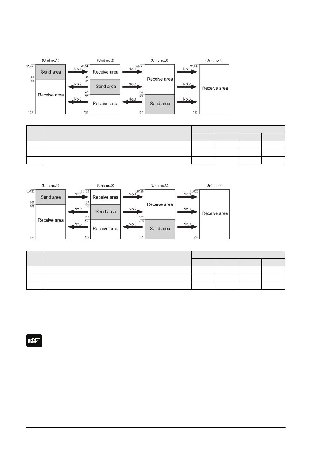
Link relay allocation
System registers
No. Name
Setting for various units
50 Range of link relays used 64 64 64 64
Starting No. of word for link relay transmission
53 Link relay transmission size 20 20 24 0
Note) No.50 (range of link relays used) must be set to the same range for all the units.
Link register allocation
System registers
No. Name
Setting for various units
Range of link registers used
54 Starting No. for link register transmission 128 128 208 128
Link register transmission size
Note) No.51 (range of link registers used) must be set to the same range for all the units.
When link areas are allocated as shown above, the No.1 send area can be sent to the No.2, No.3 and
No.4 receive areas. Also, the No.1 receive area can receive data from the No.2 and No.3 send areas.
No.4 is allocated as a receive area only, and can receive data from No.1, No.2 and No.3, but cannot
transmit it to other stations.
Note:
The PC link 1 can be used to connect with the second PC link W0 of the FP2 Multi Communication Unit
(MCU). At that time, the link relay number and link register number for the PC link can be the same
values as the FP2 (from WL64, from LD128).