7-23
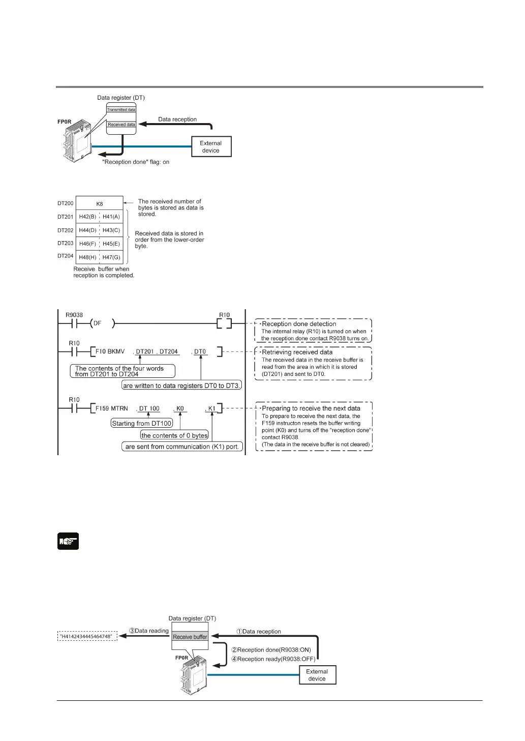
7.5.4 Receiving Data
Data input from the communication port is
stored in the receive buffer specified by the
system register, and the “reception done” flag
goes on. If the “reception done” flag is off, data
can be received at any time.
Data table for reception (receive buffer)
This is the state when the above program is executed.
DT200 to DT204 are used as the receive buffer.
System register settings are as follows:
- System register 416: K200
- System register 417: K5
Sample program for receiving data
8-byte data received in the receive buffer through the communication port 1 are copied to DT0.
The program described above is executed in the following sequence.
1) The data sent from external devices is stored in the receive buffer.
2) The “reception done” contact R9038 is turned on.
3) The received data is sent from the receive buffer to the area starting with data register DT0.
4) The F159 (MTRN) instruction is executed with no data to clear the number of received bytes and to
turn off the reception done” contact R9038. The system is now ready to receive the next data.
(The data in the receive buffer is not cleared.)
Note:
Be aware that the “reception done” flag R9038 changes even while a scan is in progress (e.g., if the
“reception done” flag is used multiple times as an input condition, there is a possibility of different
statuses existing within the same scan.) To prevent multiple read access to the special internal relay you
should generate a copy of it at the beginning of the program.
Explanatory diagram