15-4
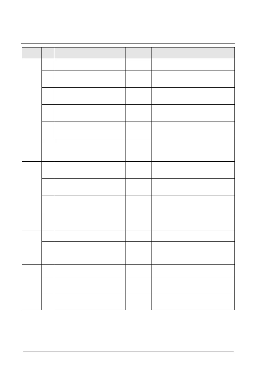
15.1.1 Table of System Registers for FP0R
No. Name
Descriptions
Hold/
Non-
hold 1
5
Starting number setting for
1008 0 to 1024
6
Hold type area starting number
setting for timer and counter
1008
0 to 1024
7
Hold type area starting number
setting for internal relays
248
0 to 256
8
Hold type area starting number
setting for data registers
0
0 to 32765
14
Hold or non-hold setting for step
ladder process
Non-hold
Hold/Non-hold
4
Previous value is held for a
leading edge detection
instruction (DF instrucion) with
Note)
Hold
Hold/
Non-hold
Hold/
Non-
hold 2
10
Hold type area starting word
number for PC(PLC) link relays
(for PC(PLC) link 0) (T32/F32)
0 0 to 64
11
Hold type area starting word
number for PC(PLC) link relays
(for PC(PLC) link 1) (T32/F32)
64 64 to 128
12
Hold type area starting number
for PC(PLC) link registers
(for PC(PLC) link 0) (T32/F32)
0 0 to 128
13
Hold type area starting number
for PC(PLC) link registers
(for PC(PLC) link 1) (T32/F32)
128 128 to 256
Action
on
error
20
Disable or enable setting for
Disabled Disabled/Enabled
23
Operation setting when an I/O
verification error occurs
Stop Stop/Continuation of operation
26
Operation setting when an
Stop Stop/Continuation of operation
Time
set-
ting
31
Wait time setting for multi-frame
6500.0
10 to 81900 ms
32
Communication timeout setting
for SEND/RECV, RMRD/RMWT
10000.0
ms
10 to 81900 ms
34
Constant value settings for scan
time
Normal
scan
0: Normal scan
0 to 600 ms: Scans once each