1-7
1.2 Restrictions on Unit Combination
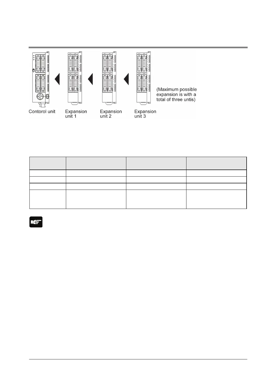
Up to three expansion units can be added on the right of the FP0R, these expansion units being either
expansion units or intelligent units.
A combination of relay output and transistor output types is also possible.
Controllable I/O points
Type of
No. of I/O points when
When the expansion unit
When the expansion unit
is a transistor output type
C10 10 points Max. 58 points Max. 106 points
C32
T32
32 points Max. 128 points Max. 128 points
Note:
- Install the FP0 thermocouple unit on the right side of all other expansion units.
- If it is installed on the left side, the total precision will deteriorate.
- Install the FP0 CC-Link slave unit on the right side of all other expansion units. There is no expansion
connector on the right side.
- Install the FP0 RTD unit on the right side of all other expansion units.