Home
Panasonic
Controller
FP0R
Page 258 (C16 Control Unit (MIL Connector))
Panasonic FP0R - C16 Control Unit (MIL Connector)
348 pages
Manual
Save Page as PDF
To Next Page
To Next Page
To Previous Page
To Previous Page
Loading...
14
-4
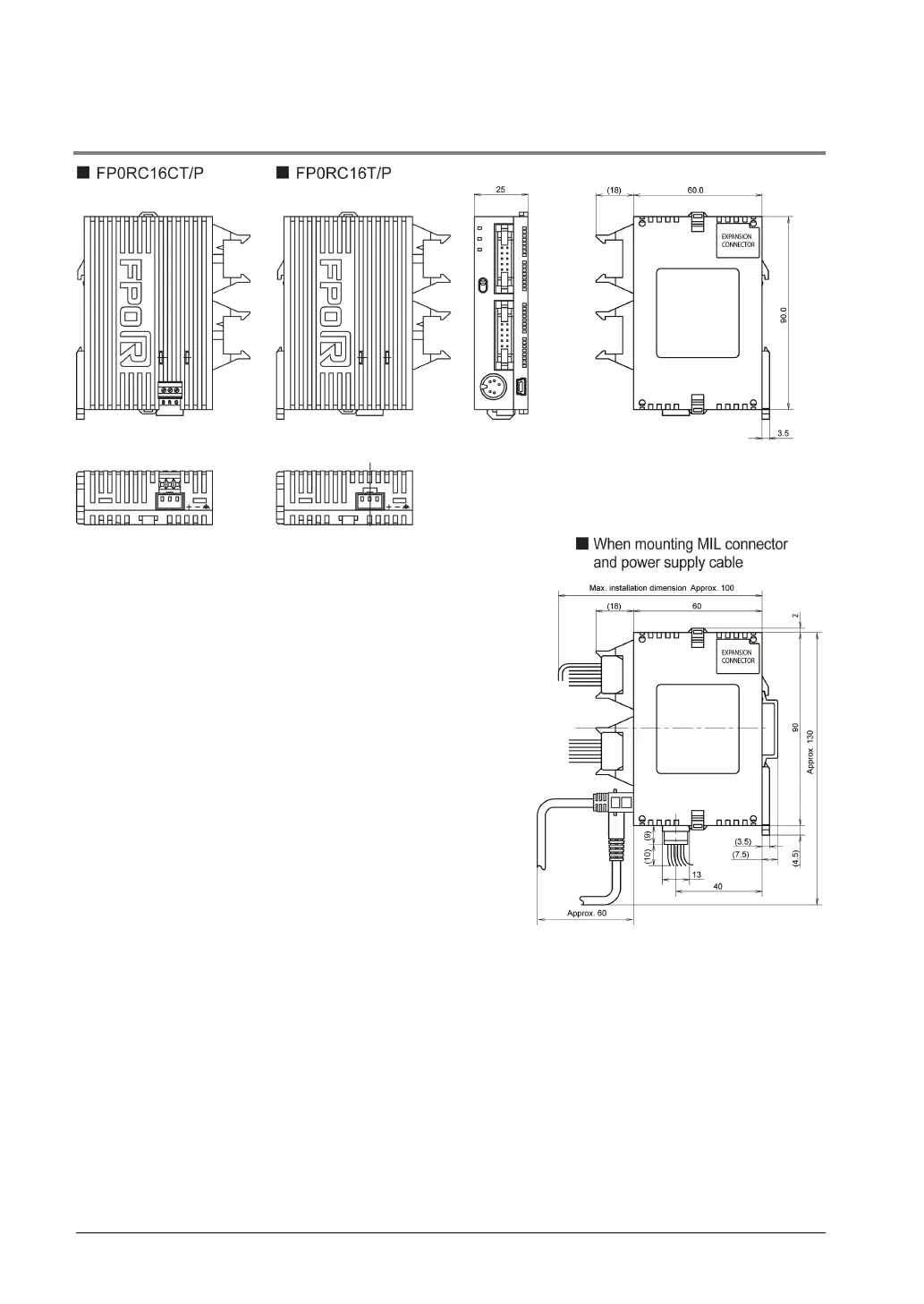
14.1.3
C16 Control Uni
t (MIL Connector)
(Unit: mm)
Note) As for t
he expansion unit, ref
er to the dimensions onl
y.
Target expansi
on units: E16X, E16YT
, E16YP, E16T, E16P,
E8X, E8YT, E8YP
257
259
Table of Contents
Main Page
Default Chapter
2
Safety Precautions
2
Warning
2
Table of Contents
3
Before You Start
7
Operating Environment
7
Power Supply
7
Static Electricity
7
Programming Tool Restrictions
8
When Using FP0 Programs
9
How to Use FP0 Compatibility Mode
11
Restrictions on Switching to FP0 Compatibility Mode
11
Tools Supporting FP0 Compatibility Mode
11
When Using the FP0R in the same Specifications as FP0
11
F170(PWM) Instruction Specifications
12
P13(PICWT) Instruction Specifications
12
Real Number Calculation Process
13
F169(PLS) Instruction Specifications
13
F168(SPD1) Instruction Specifications
13
F144(TRNS) Instruction Specifications
13
1 Functions and Restrictions of the Unit
15
Unit Types
16
FP0R Control Units
16
FP0 Expansion Units
18
Intelligent Units
19
Link Units
19
Power Supply Unit
20
Options
20
Repair Parts
20
Restrictions on Unit Combination
21
Controllable I/O Points
21
Programming Tools
22
Required Tools for Programming
22
Software Environment and Suitable Cable
22
Programming Tool Software
22
Type of Computer and Suitable Cable
23
D-Sub Connector Cable
23
USB Cable
23
2 Specifications and Functions of Control Unit
25
Part Names and Functions
26
Operation Monitor Leds
26
RUN/PROG. Mode Switch
27
USB Connector (Mini-USB B Type (5-Pin))
27
Tool Port (RS232C)
27
Input and Output Specifications
28
Limitations on Number of Simultaneous Input on Points
28
Circuit Diagram
28
Transistor Output Specifications
29
Limitations on Number of Simultaneous Output on Points
29
Relay Output Specifications (C10/C14)
30
Terminal Layout Diagrams
31
Functions of T32 Control Unit
34
Memory Backup Function
34
Backup of Operation Memory
34
Built-In Backup Battery
35
Time the Built-In Backup Battery Can be Used (Backup Time)
35
Relation between Charging Time and Backup Time
35
Predicted Life of Built-In Backup Battery
35
Area of Clock/Calendar
36
Setting of Clock/Calendar Function
36
Setting Using a Programming Tool
36
Setting and Changing Using Program
37
Example Showing the Date and Time Being Written
37
Example Showing the Clock/Calendar Being Used
37
Sample Program for Fixed Schedule and Automatic Start
37
3 Expansion
39
Expansion Method
40
Part Names and Functions
41
Input and Output Specifications
42
Terminal Layout Diagram
45
4 I/O Allocation
49
Expression of Numbers for Input/Output Relays
50
Regarding I/O Number
50
I/O Allocation for FP0R Control Unit
51
I/O Numbers of FP0/FP0R Expansion Unit
52
5 Installation and Wiring
53
Installation Environment and Space
54
Measures Regarding Heat Discharge
54
Attachment to DIN Rail and Removal from DIN Rail
55
Installation Space
55
Procedure of Installation
55
Procedure of Removal
55
Installation Using the Optional Mounting Plate
56
When Using the Slim Type FP0 Mounting Plate (AFP0803)
56
When Using the Flat Type Mounting Plate (AFP0804)
57
Power Supply Type
58
Power Supply Wire
58
Power Supply Wiring for the Unit
58
Wiring of Power Supply
58
Exclusive Grounding
59
Grounding
59
In Situations of Excess Noise
59
Precaution When Using LED-Equipped Reed Switch
60
Precaution When Using Two-Wire Type Sensor
60
Voltage Output Type
60
Wiring of Input and Output
60
Precaution When Using LED-Equipped Limit Switch
61
Output Wiring
62
Protective Circuit for Inductive Loads
62
When Using an AC Inductive Load (Relay Output Type)
62
When Using an DC Inductive Load
62
Connector for Loose-Wire Cable
63
Suitable Wires (Twisted Wire)
63
Supplied Connector and Suitable Wires
63
Wiring of MIL Connector Type
63
Wiring Method
64
Attached Terminal Block/Suitable Wires
65
Pole Terminal
65
Terminal Block Socket
65
Wiring of Terminal Block Type
65
Notes for Wiring
66
Wiring of Molex Connector Type
67
Suitable Wires and Wiring Method
68
Terminal Block/Suitable Wires
68
Wiring of COM Port
68
For Tightening the Terminal Block
69
Connection of COM Port (RS485 Type)
70
Selection of Transmission Cables (RS485 Type)
70
Baud Rate Setting (RS485 Type)
71
Setting of Baud Rate Switches
71
Setting Using FPWIN GR
71
System Register Settings
71
Momentary Power Failures
72
Precautions Regarding System Design
72
Protection of Power Supply and Output Sections
72
Safety Measures
72
6 Preparation of USB Port
73
USB Connection
74
Precautions When Connecting PLC with USB Port
74
Installation of USB Driver
75
Restrictions on USB Communication
75
Procedure of Installing the Driver
75
Confirming COM Ports
82
How to Confirm COM Port
82
Communication with Programming Tool
83
7 Communication
85
Functions and Types
86
Communication Modes and Communication Ports
86
Computer Link
86
General-Purpose Serial Communication
86
PC(PLC) Link
87
Modbus Rtu
87
Communicaton Port Type
88
Tool Port
88
USB Port
88
COM Port
88
Communication Specifications
89
MEWTOCOL Master Function
91
MEWTOCOL Slave Function
91
Computer Link
91
Command and Response
92
MEWTOCOL-COM Sketch
92
Command Message
93
Header (Start Code)
93
Unit Numbe
93
Check Code
93
Response Message
94
Commands to be Used
95
Setting Communication Parameters
96
Tool Port/Com Port
96
Setting with FPWIN GR
96
Dialog Box of PLC System Register Setting
96
Communication (MEWTOCOL Slave Function)
97
Programming of Computer Link
97
Example of Connection to the Computer <1:1 Communication>
97
1:N Communication (MEWTOCOL Slave Function)
98
Setting of Unit Numbers
98
Setting System Registers
98
MEWTOCOL Master
99
Setting in Compatiblity Mode with FP0 (FP0 Compatibility Mode)
101
Usable Communication Ports on FP0R (FP0 Compatibility Mode)
101
COM Port (RS232C Port) Settings
101
Sending Data
102
Receiving Data
102
General-Purpose Serial Communication
102
Programming Example of General-Purpose Serial Communication
103
Data to be Sent/Received with FP0R
104
Data Table for Transmission (Send Buffer)
105
Sample Program for Sending Data
105
Transmission Process
106
Data Table for Reception (Receive Buffer)
107
Sample Program for Receiving Data
107
Explanation of Data Table
108
Reception Process
108
For Repeated Reception of Data
108
Flag Operation in Serial Communication
109
Dialog Box of PLC System Register Setting (Tool Port Selection Screen)
113
Connection with 1:1 Communication
114
1:N Communication (General-Purpose Serial Communication)
115
Settings in Compatibility Mode with FP0 (FP0 Compatibility Mode)
116
PC(PLC) Link Function
118
Operation of PLC Link
119
Link Relay
119
Link Register
119
Setting Communication Parameters: PC(PLC) Link
121
Settings for Baud Rate and Communication Format
121
Link Area Allocation
122
System Registers
122
Link Area Configuration
122
Example of Allocation
123
Link Relay Allocation
123
Link Register Allocation
123
Partial Use of Link Areas
125
Avoid Overlapping Send Areas
126
Example of Link Relay Allocations
126
Invalid Allocations
126
Setting the Largest Unit Number for PC(PLC) Link
127
Setting PC(PLC) Link Switching Flag
127
Monitoring
128
Transmission Assurance Relays
128
Operation Mode Relays
128
PLC Link Transmission Error Relay R9050
128
PC(PLC) Link Response Time
129
Programming Example of SYS1 Instruction
131
Error Detection Time for Transmission Assurance Relays
132
MODBUS RTU Communication
133
Overview of Functions
133
About MODBUS RTU
133
Master Function
133
MODBUS RTU Command Message Frame
134
Response in Normal Status
134
Response in Abnormal Status
134
Error Code Contents
134
Supported Commands
135
MODBUS Master
137
8 High-Speed Counter, Pulse Output and PWM Output Functions
141
Overview of each Functions
143
Three Pulse Input/Output Functions
143
Pulse Output Function
143
PWM Output Function
143
Performance of Built-In High-Speed Counter
144
Number of Channel
144
Counting Range
144
Function Specifications and Restricted Items
145
High-Speed Counter Function
145
Functions Used and Restrictions
147
Simplified Chart - Maximum Counting Speed of High-Speed Counter
147
Max. Counting Speed
148
FP0R Pulse Output Performance
149
Independent Control
149
Interpolation Control
149
Overview of High-Speed Counter Function
150
Input Modes and Count
150
Minimum Input Pulse Width
151
Count for Reset Input
151
Instructions Used with High-Speed Counter Function
152
High-Speed Counter Control Instruction
152
High-Speed Counter/Pulse Output Control Flag Area of FP0R
153
High-Speed Counter Control Flag Monitor Area
153
Elapsed Value Write and Read Instruction
154
Target Value Match on Instruction
154
Input Pulse Measurement Instruction
155
High-Speed Counter Control Flag
156
Allocation and Role of High-Speed Counter Control Flag
156
Operation of High-Speed Counter Control Flag
156
Sample Program
157
Positioning Operations with a Double Speed Inverter
158
Program
159
Overview of Pulse Output Function
160
Types of Pulse Output Method and Operation Modes
161
Clockwise/Counter-Clockwise Output Method
161
Pulse/Direction Output Method
161
Operation Mode
162
Incremental
162
Absolute
162
Double Pulse Input Driver
163
Single Pulse Input Driver
163
Table of I/O Allocation
164
Pulse Output Control Instructions
165
Operations Executable by Pulse Output Control Instruction
165
FP0R Pulse Output Control Flag Area
166
Pulse Output Control Flag Monitor Area
166
Forced Stop, Deceleration Stop Instruction
167
Elapsed Value Read and Write Instruction
168
Elapsed Value Area
168
JOG Operation Instruction
169
Operation Modes of JOG Operation
169
Sample Program JOG Operation: Type 0 (no Target Value)
170
Sample Program JOG Operation: Type 1 (with Target Value)
172
Home Return Instruction
174
Operation Modes of Home Return Operation
174
Sample Program: Home Return
175
Trapezoidal Control Instruction
177
Control Method of Trapezoidal Control Instruction
177
Sample Program: Trapezoidal Control Type 0 (F171)
178
Precautions During Programming
179
Speed Change after Starting Trapezoidal Control Type 0 (F171)
180
Speed Change after Starting Trapezoidal Control Type 1 (F171)
181
Precautions When Changing Speed (Common to F171 and F172)
182
Pulse Output Control Area
182
JOG Positioning Control Instruction (F171)
183
Control Method of JOG Positioning Control Instruction
183
Sample Program: JOG Positioning Operation: Type 0
185
Sample Program: JOG Positioning Operation: Type 1
187
JOG Positioning Control Type 0 - Change Speed (F171)
189
Data Table Control Instruction (F174)
190
Linear Interpolation Control Instruction (F175)
192
Difference in Acceleration/Deceleration between Instructions
194
Acceleration/Deceleration Characteristics of each Instruction
194
Pulse Output Instruction Flag
197
Common Precautions for Pulse Output Instructions
197
Allocation and Role of Pulse Output Instruction Flag
197
Operation of Pulse Output Instruction Flag
197
PWM Output Function
198
9 Security Functions
199
Password Protect Function
200
Characters Usable for Password
200
Setting Using Programming Toolr
201
Security Information Dialog Box
201
Current Status
201
Available Retry Counts
201
How to Prohibit Access with Password
202
How to Permit Access with Password
203
How to Cancel the Password Protection
204
How to Cancel the Password Protection (Programs Are Retained.)
204
How to Force Cancel
205
Upload Protection
206
Setting Method
206
Overview of Program Upload Protection Function
206
Interaction with the Password Protect Function
206
Setting Function for FP Memory Loader
207
Limited Distribution Function
207
Upload Protection Setting Function
207
Version Check List
209
Status of PLC that Program Has Been Downloaded
209
Table of Security Settings/Cancel
210
10 Other Functions
211
P13 (PICWT) Instruction
212
Restrictions on the Number of Writing
212
Sampling Trance Function
213
Details of Sampling Trace Function
213
How to Stop Sampling
213
How to Use Sampling Trace
214
Operation Image of Sampling Trace
214
Sampling by Instruction
215
Read Data by Trigger
215
Time Constant Processing
216
Input Time Constant Setting Function and Applicable Models
216
11 Self-Diagnostic and Troubleshooting
217
LED Display for Status Condition
218
Operation Mode When an Error Occurs
218
Self-Diagnostic Function
218
“PLC System Register” Setting Menu on Programming Tool Software
218
If ERROR/ALARM LED Is Flashing
219
PLC Status Dialog Box
219
Status Display Dialog Box
219
Troubleshooting
219
Using FPWIN GR/FPWIN Pro
220
ALL Leds Are off
221
If ERROR LED Is on
221
Diagnosing Output Malfunction
222
A Protect Error Message Appears
223
Set PLC Password Dialog Box
223
Using FPWIN Pro
223
When a Password Function Is Used
223
PROG Mode Does Not Change to RUN
224
Operation Errors
225
Operation Mode When an Operation Error Occurs
225
Outline of Operation Errors
225
Types of Operation Error
225
Dealing with Operation Errors
226
Points to Check in Program
226
12 Precautions During Programming
227
Use of Duplicated Output
228
What Is Duplicated Output?
228
How to Check for Duplicated Use
228
Enabling Duplicated Output
228
When Output Is Repeated with an OT, KP, SET or RST Instruction
229
The Output Is Determined by the Final Operation Results
229
Handling Index Registers
230
Index Registers
230
Memory Areas Which Can be Modified with Index Registers
230
Example of Using an Index Register
231
Instructions of Leading Edge Detection Method
232
Leading Edge Detection Method
232
How to Perform Leading Edge Detection
232
Precautions Using Instruction Which Performs Leading Edge Detection
232
Operation and Precautions When RUN Starts
233
Operation of First Scan after RUN Begins
233
Precautions When Using a Control Instruction
234
Using the DF Instruction between MC and MCE Instructions
234
Using the CT Instruction between JP and LBL Instructions
234
Precautions for Programming
235
Programs Which Are Not Executed Correctly
235
Examples in Which the above Programs Are Rewritten Correctly
235
Rewrite Function During RUN
236
Operation of Rewrite During RUN
236
How Operation of Rewrite During RUN Is Performed
236
Operation During Rewrite
236
Cases Where Rewriting During Run Is Not Possible
237
When the Timeout Error Message Is Indicated
237
When Ladder Symbol Mode
237
When Boolean Mode
237
During the Forced Input/Output Operation
238
The High-Speed Counter will Continue to Count
238
Interrupt Restrictions
238
Procedures and Operation of Rewrite During RUN
239
Processing During Forced Input and Output
241
Processing of External Input (X)
241
Processing of External Output (Y)
241
Processing of Timer (T) and Counter (C)
241
13 Specifications
243
Table of Specifications
244
Control Specifications
246
I/O Number Allocation
250
I/O Numbers for FP0 Expansion Unit
251
Relays, Memory Areas and Constants
252
Power Supply Unit and I/O Link Unit Specifications
253
14 Dimensions and Others
255
C10/C14 Control Unit (Terminal Block)
256
Dimensions
256
C10/C14 Control Unit (Molex Connector)
257
C16 Control Unit (MIL Connector)
258
C32/T32/F32 Control Unit (MIL Connector)
259
I/O Link Unit
260
When Using DIN Rail
260
Cable/Adapter Specifications
261
15 Appendix
263
Precaution for System Registers
264
Type of System Registers
264
What Is the System Register Area
264
Checking and Changing the Set Value of System Register
265
Precautions for System Register Setting
265
Using Programming Tool Software
265
Table of System Registers for FP0R
266
Table of Special Internal Relays for FP0R
272
Table of Special Data Registers for FP0R
282
Table of Basic Instructions
301
Table of High-Level Instructions
309
Difference in ERROR Display
329
Error Confirmation When ERROR Turns on
329
Table of Error Codes
329
When a Syntax Check Error Is Detected
329
Clearing the Self-Diagnostic Error
330
MEWTOCOL-COM Transmission Errors
330
Self-Diagnostic Error
330
When a Self-Diagnostic Error Occurs
330
Table of MEWTOCOL-COM Communication Error
340
MEWTOCOL-COM Communication Commands
342
Hexadecimal/Binary/Bcd
343
ASCII Codes
344
Related product manuals
Panasonic FP0
382 pages
Panasonic FP0H
200 pages
Panasonic FP0-A21
42 pages
Panasonic FP0-A80
42 pages
Panasonic FP0 Series
27 pages
Panasonic FP0R Series
92 pages
Panasonic FP2
102 pages
Panasonic FPG-PP22
332 pages
Panasonic FPG-PP21
332 pages
Panasonic FP Series
1345 pages
Panasonic FP-X0 L14R
290 pages
Panasonic FPG-C24R2H
440 pages