7-38
7.6.4 Link Area Allocation
The link relays and link registers to be used in the PC(PLC) link are allocated in the link area of the CPU
unit. Link area allocations are specified by setting the system registers of the CPU unit.
System registers
No. Name
Default
Set value
For
PC
(PLC)
link 0
Range of link relays used for PC(PLC) link
Range of link data registers used for PC(PLC) link
Starting number for link relay transmission
Link relay transmission size
Starting number for link data register transmission
Link data register transmission size
46 PC(PLC) link switch flag Normal Normal: 1st half
47 Maximum unit number setting for MEWNET-W0
16 1 to 16
For
PC
(PLC)
link 1
46 PC(PLC) link switch flag Normal Normal: 1st half
Range of link relays used for PC(PLC) link
Range of link data registers used for PC(PLC) link
Starting number for link relay transmission
Link relay transmission size
Starting number for link data register transmission
Link data register transmission size
57 Maximum unit number setting for MEWNET-W0
16 1 to 16
Note) The same maximum unit number should be specified for all the PLCs connected in the PC(PLC)
link.
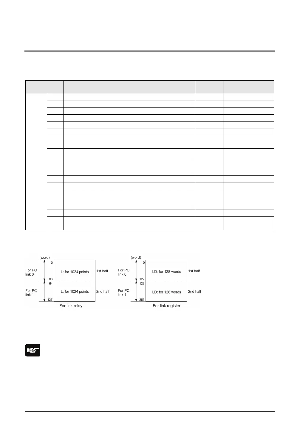
Link area configuration
- Link areas consist of link relays and link registers, and are divided into areas for PC(PLC) link 0 and
PC(PLC) link 1 and used with those units.
- The link relay which can be used in an area for either PC(PLC) link 0 or PC(PLC) link 1 is maximum
1024 points (64 words), and the link register is maximum 128 words.
Note:
The PC link 1 can be used to connect with the second PC link W0 of the FP2 Multi Communication Unit
(MCU). At that time, the link relay number and link register number for the PC link can be the same
values as the FP2 (from WL64, from LD128).