12-5
12.2.3 Example of Using an Index Register
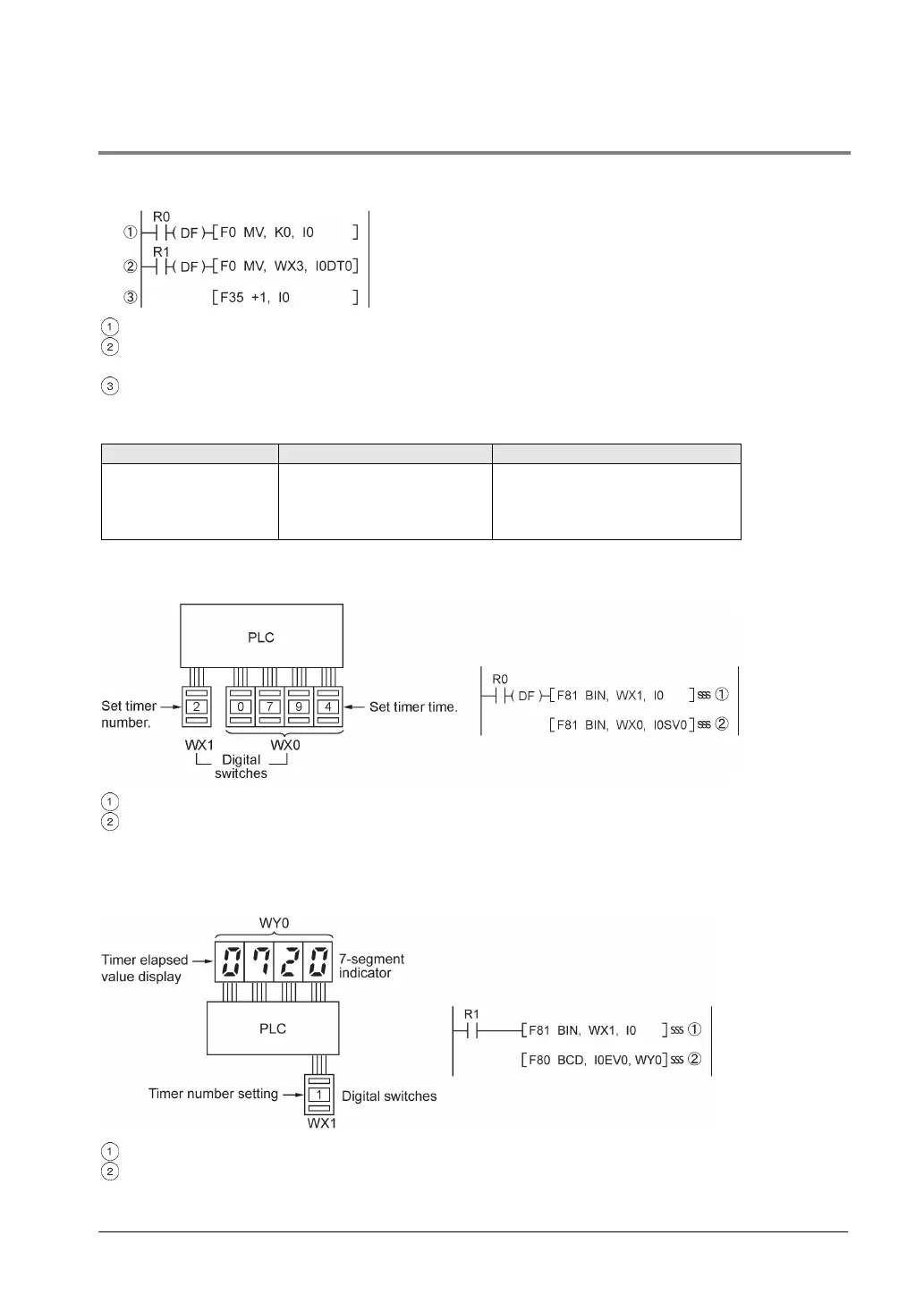
Repeatedly reading in external data
<Example> Writing the contents of input WX3 to a sequence of data registers beginning from DT0.
When R0 turns on, 0 is written to index register I0.
When the R1 turns on, the contents of input WX3 is transferred to the data register specified by
I0DT0.
Add 1 to I0.
In this case, the contents of I0 will change successively, and the destination data register will be as
follows.
Destination data register
1st
2nd
3rd
0
1
2
DT0
DT1
DT2
Inputting and outputting data based on a number specified by an input
<Example 1> Setting a timer number specified by a digital switch
Convert the BCD timer number data in WX1 to binary and set it in index register I0.
Convert the BCD timer set value in WX0 to binary and store in the timer set value area SV specified
by contents of I0.
<Example 2> Taking external output of the elapsed value in a timer number specified by a digital
switch
Convert the BCD timer number data in WX1 to binary and set it in index register I0.
Convert the elapsed value data EV in the timer specified by I0 to BCD, and output it to output relay
WY0.