13-10
13.3 Relays, Memory Areas and Constants
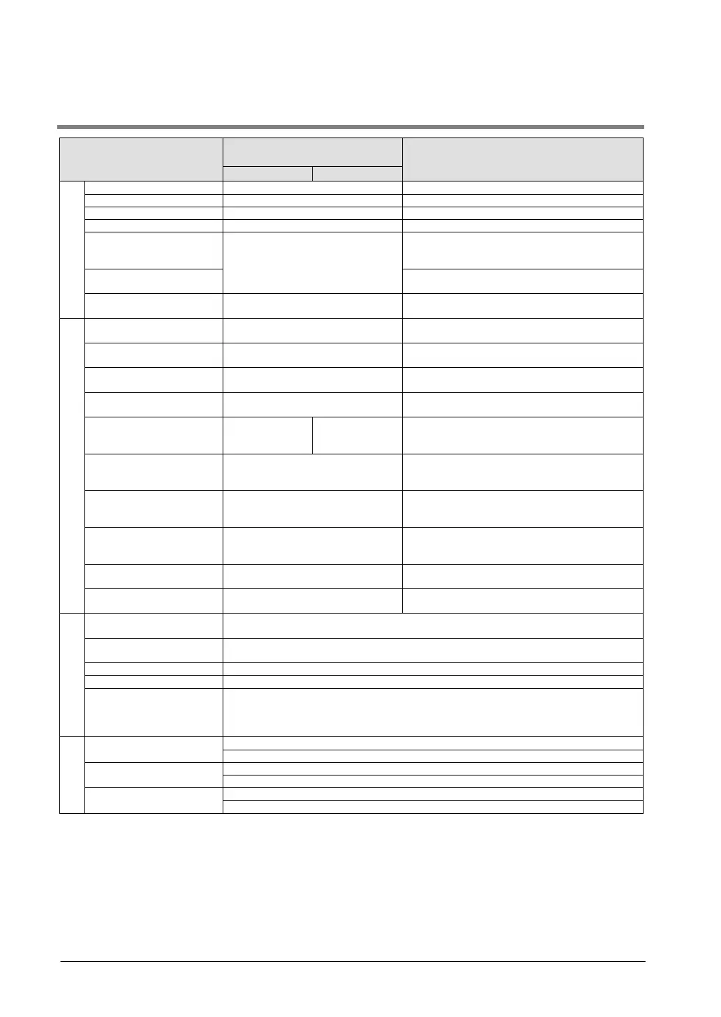
Item
Number of points and range of
memory area available for use
Function
Relay
External input
Note1)
(X)
1760 points (X0 to X109F)
Turns on or off based on external input.
External output
Note1)
(Y)
1760 points (Y0 to Y109F)
Externally outputs on or off state
Internal relay
Note2)
(R)
4096 points (R0 to R255F)
Relay which turns on or off only within program.
2048 points (L0 to L127F)
This relay is a shared relay used for PLC link.
Timer
Note2)
(T)
1024 points (T0 to T1007/C1008 to
C1023)
Note3)
This goes on when the timer reaches the
specified time. It corresponds to the timer
Counter
Note2)
(C)
This goes on when the counter increments. It
corresponds to the counter number.
Special internal relay (R) 224 points (from R9000)
Relay which turns on or off based on specific
conditions and is used as a flag.
Memory area
External input
Note1)
(WX) 110 words (WX0 to WX109)
Code for specifying 16 external input points as
one word (16 bits) of data.
External output
Note1)
(WY)
110 words (WY0 to WY109)
Code for specifying 16 external output points as
one word (16 bits) of data.
Internal relay
Note2)
(WR) 256 words (WR0 to WR255)
Code for specifying 16 internal relay points as
one word (16 bits) of data.
Link relay (WL) 128 words (WL0 to WL127)
Code for specifying 16 link relay points as one
word (16 bits) of data.
Data register
Note2)
(DT)
(DT0 to
(DT0 to
Data memory used in program. Data is handled
in 16-bit units (one word).
Link register
Note2)
(LD) 256 words (LD0 to LD255)
This is a shared data memory which is used
within the PLC link. Data is handled in 16-bit
Timer/Counter set value
area
Note2)
(SV)
1024 words (SV0 to SV1023)
Data memory for storing a target value of a timer
and setting value of a counter. Stores by
Timer/Counter elapsed
value area
Note2)
(EV)
1024 words (EV0 to EV1023)
Data memory for storing the elapsed value
during operation of a timer/counter. Stores by
timer/counter number.
Special data register
(DT)
440 words
Data memory for storing specific data. Various
settings and error codes are stored.
Index register (I) 14 words (I0 to ID)
Register can be used as an address of memory
area and constants modifier.
Control
Master control relay
points (MCR)
256 points
Number of labels
256 points
Number of interrupt
programs
C10: 11 programs (6 external input points, 1 periodical interrupt point, 4-pulse match
points)
Other than C10: 13 programs (8 external input points, 1 periodical interrupt point, 4-
pulse match points)
Constant
Decimal constants
K-32, 768 to K32, 767 (for 16-bit operation)
K-2, 147, 483, 648 to K2, 147, 483, 647 (for 32-bit operation)
Hexadecimal constants
H0 to HFFFF (for 16-bit operation)
H0 to HFFFFFFFF (for 32-bit operation)
Floating point type (F)
F-1.175494 x 10
-38
to F-3.402823 x 10
38
F 1.175494 x 10
-38
to F 3.402823 x 10
38
Note1) The number of points noted above is the number reserved as the calculation memory. The actual number of
points available for use is determined by the hardware configuration.
Note2) There are two types, one is the hold type that the last state is stored even if the power supply turns off or the
mode is changed to PROG. mode from RUN mode, and the other is the non-hold type that the state is reset.
For C10/C14/C16/C32: The hold type areas and non-hold type areas are fixed. For information on the
sections of each area, refer to the performance specifications.
For T32/F32: The settings of the hold type areas and non-hold type areas can be changed using the system
registers.
On T32, if the battery has run out, the data in the hold area may be indefinite (Not cleared to 0)
Note3) The points for the timer and counter can be changed by the setting of system register 5. The number given in
the table are the numbers when system register 5 is at its default setting.