7-22
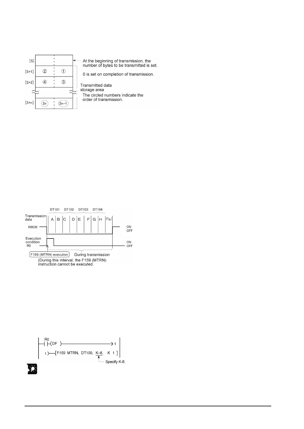
Explanation of data table
The data table for transmission starts at the data register specified in S.
- Use an F0 (MV) or F95 (ASC) instruction to write the data to be transmitted to the transmission data
storage area specified in S.
Transmission process
When the execution condition of the F159 (MTRN) instruction turns on and the “transmission done” flag
R9039 is on, operation is as follows:
1. The number of transmission data [N] is preset in the start address of send buffer [S]. The “reception
done” flag R9038 is turned off, and the reception data number is cleared to 0.
2. The set data is transmitted in order from the lower-order byte in S+1 of the table.
- During transmission, the “transmission done” flag R9039 turns off.
- If system register 413 is set to header (start code) with STX, the header is automatically added to the
beginning of the data.
- The terminator (end code) specified in system register 413 is automatically added to the end of the data.
3. When all of the specified quantity of data has been transmitted, the S value is cleared to 0 and the
“transmission done” flag R9039 turns on.
When you do not wish to add the terminator (end code) during transmissions:
- Specify the number of bytes to be transmitted using a negative number.
- If you also do not wish to add a terminator to received data, set system register 413 to “Terminator -
None”.
Programming example:
The following program transmits 8 bytes of data without adding the terminator.
Key Point:
- Do not include the terminator (end code) in the transmission data. The terminator is added
automatically.
- When “STX exist” is specified for the header (start code) in system register 413, do not add the header
to the transmission data. The header is added automatically.