7-20
Data to be sent/received with FP0R
Remember the following when accessing data in the FP0R send and receive buffers:
- If a header has been chosen in the communication format settings, the code STX (H02) will
automatically be added at the beginning of the data begin sent.
- The data without the code STX at the reception is stored in the receive buffer, and the “reception done”
flag turns on when the terminator (end code) is received. When the terminator has been set to “None”,
the “reception done” flag does not work.
However, if the code STX is added in the middle of the data, the number of received byte is cleared to
0, and the data is stored from the beginning of the receive buffer again.
- A terminator is automatically added to the end of the data being sent.
- There is no terminator on the data stored in the receive buffer.
Sending data:
Data written to the send buffer will be sent just as it is.
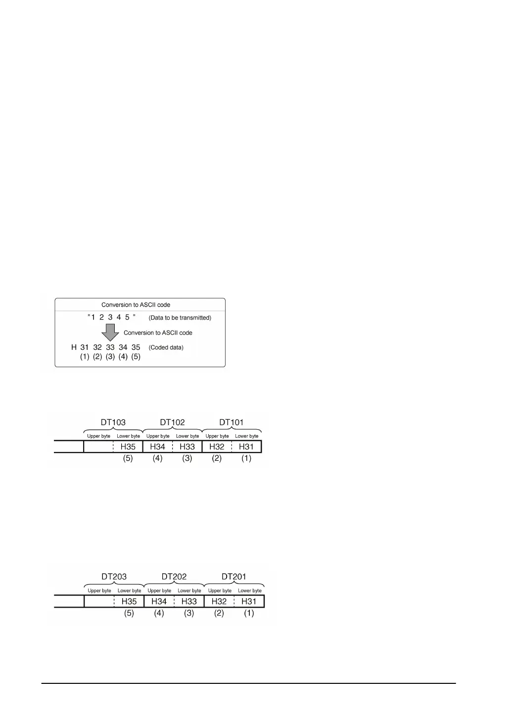
Example:
The data “12345” is transmitted as an ASCII code to an external device.
1. Data sent using the F95 (ASC) instruction should be converted to ASCII code data.
2. If DT100 is being used as the start address of send buffer, data will be stored in sequential order in
the data registers starting from the next register (DT101), in two-byte units consisting of the upper and
the lower byte.
Receiving data:
The data of the receive area being read is ASCII code data.
Example:
The data “12345
C
R
” is transmitted from a device with RS232C port.
If DT200 is being used as the receive buffer, received data will be stored in the registers starting from
DT201, in sequential order of first the lower byte and then the upper byte.