Common Measurement Settings
R&S
®
FSVA3000/ R&S
®
FSV3000
356User Manual 1178.8520.02 ─ 01
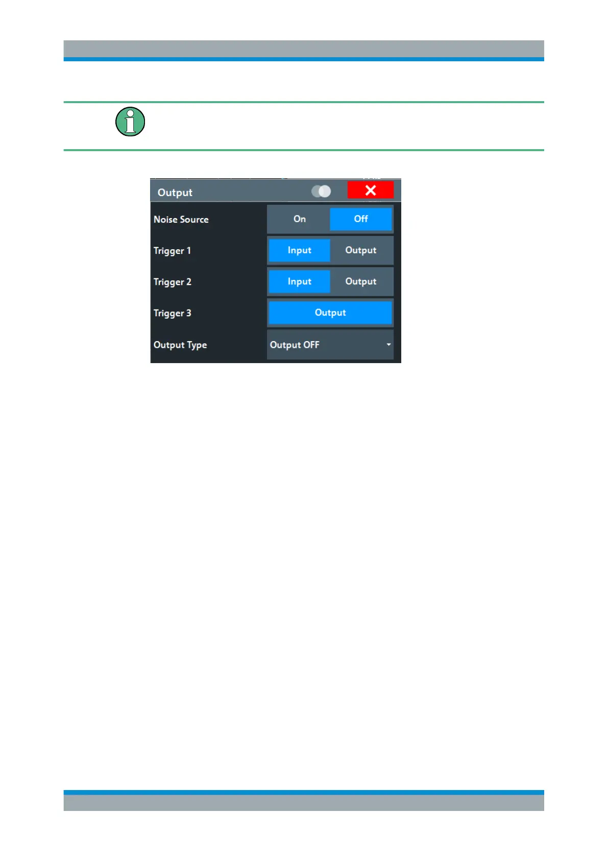
Providing trigger signals as output is described in detail in Chapter 8.2.1.2, "Receiving
and Providing Trigger Signals", on page 310 and Chapter 8.2.9, "How to Output a Trig-
ger Signal", on page 357.
Trigger 1/2
Defines the usage of the variable Trigger Input/Output connectors, where:
"Trigger 2" : Trigger Input/Output connector on the front panel
"Trigger 3" : Trigger 3 Input/Output connector on the rear panel
Defines the usage of the variable Trigger Aux connector on the rear panel.
(Trigger 1 is INPUT only.)
"Input"
The signal at the connector is used as an external trigger source by
the R&S FSV/A. Trigger input parameters are available in the "Trig-
ger" dialog box.
"Output"
The R&S FSV/A sends a trigger signal to the output connector to be
used by connected devices.
Further trigger parameters are available for the connector.
Remote command:
OUTPut<up>:TRIGger<tp>:DIRection on page 917
Output Type ← Trigger 1/2
Type of signal to be sent to the output
"Trigger Off"
Deactivates the output. (Only for Trigger 3, for which only output is
supported.)
"Device Trig-
gered"
(Default) Sends a trigger when the R&S FSV/A triggers.
"Trigger
Armed"
Sends a (high level) trigger when the R&S FSV/A is in "Ready for trig-
ger" state.
This state is indicated by a status bit in the STATus:OPERation reg-
ister (bit 5), as well as by a low-level signal at the AUX port (pin 9).
For details, see "STATus:OPERation Register" on page 671 and the
R&S FSV/A Getting Started manual.
Data Input and Output

 Loading...


