B245/B276/B277/B268/B269 Service Manual 18-Jan-06
215
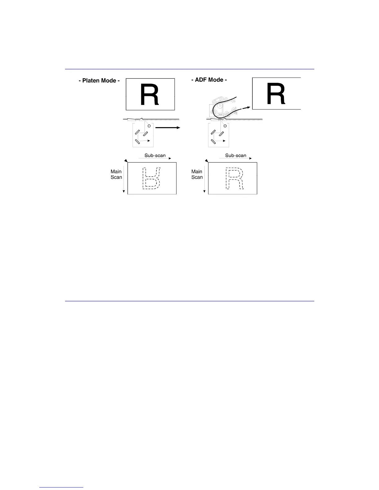
Mirroring for ADF Mode
When making copies using the ADF, the magnification circuit creates a mirror image. This is
because the scanning start position along the main scan direction in ADF mode is at the
opposite corner of platen mode.
In platen mode, the original is placed face down on the exposure glass. The main scan start
position is at corner [A], and the scanner moves down the page. In ADF mode, the ADF feeds
the leading edge of the original to the DF exposure glass. Therefore as mentioned above, the
main scan start position will be at the opposite corner.
To create the mirror image, the IPU stores each line in LIFO (Last In First Out) memory.
Filtering
Overview
There are several software filtering processes for enhancing the desired image qualities of
the selected original mode. There are three MTF filters, a smoothing filter, independent dot
erase, and line width correction. Each can be used only when certain modes are selected
(details below) and are automatically applied.
The strength levels for the MTF are controlled by SP 4932. The levels for line width correction
and independent dot erase are controlled by SP 4927 and 4928, respectively.
The MTF filters bring out sharpness. The three MTF filters are Edge, Solid Image and Low ID
Line. Line width correction adjusts the line width. Independent dot erase removes unwanted
dots from the image.
MTF Filter Adjustment - Edge
In order to determine whether a given dot is part of an edge or not, the IPU checks all
surrounding dots (vertical, horizontal, and diagonal). If the IPU determines that the dot is part
 Loading...