B245/B276/B277/B268/B269 Service Manual 18-Jan-06
74
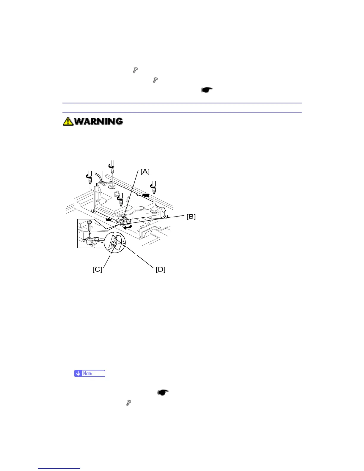
2. Two rubber bushings [A]
3. Laser unit cover [B] (
x 1)
4. Polygonal mirror motor [C] (
x 4)
5. After reassembling, adjust the image quality (
p.111).
Laser Unit Alignment Adjustment
Reinstall the copy exit tray before you turn the main switch on. The laser
beam may go out of the copier when the copy exit tray is not installed. The
laser beam can seriously damage your eyes.
1. Start the SP mode.
2. Select SP 5902 1 and output the ‘Trimming Area’ pattern (pattern 10).
3. Make sure that the four corners of the pattern make right angles:
If they make right angles, you do not need to adjust the laser unit alignment.
If they do not make right angles, go on to the next step.
4. Check the screw position on the lever [B].
If the screw is in the hole [C], go on to the next step.
If the screw is in the slot [D], loosen the screw on the lever, loosen the four screws on
the laser unit, and go on to step 9.
The initial position of the screw is in hole [C].
5. Four screws in the laser unit (
p.71)
6. Remove the lever (
x 1), confirm the position of the hole beneath the slot [D],
and reinstall the lever.