11
2017 Page 28 5IN2413 B
Main Panel Jumper Setting
On the main panel PCB, set the following jumpers as required.
JMP 2 (UO1) jumper: For configuring the UO1 (utility output 1) connection
characteristics for powering an external self-powered device, such as a siren.
See Placing the JMP 2 (UO1) Jumper, page 35.
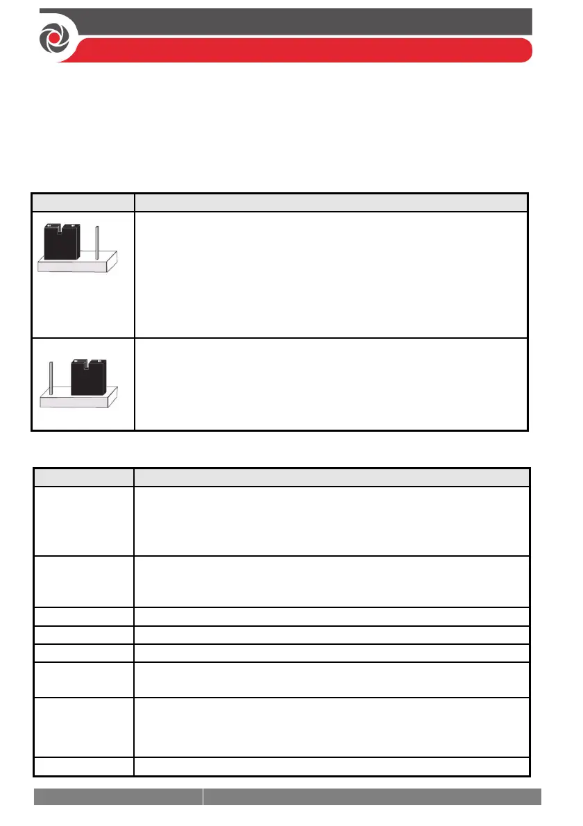
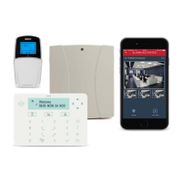
JMP 3 (Non Protect) jumper: To configure battery discharge protection (see below):
JMP 3 Position Description
(This position can
also be without a
jumper)
[Default] Enabled (Protect): Battery “deep discharge protection” is
enabled, meaning if a continuous AC power outage occurs, the system
automatically disconnects the backup battery in order to prevent a
deep discharge that may damage the battery (protection range is
between 7 VDC and 8.8 VDC).
NOTE: In this position, the system will not start to operate from a
battery power supply, unless there is power from the mains first.
Disabled (Non-protect): Battery “deep discharge protection” is
disabled; the battery may be totally discharged during continuous AC
failure, thus battery replacement may be required.
NOTE: In this position, the system will start to operate from a battery
power supply whether it is receiving power from the mains or not.
Describing Connectors & Ports on the Main Panel PCB
Connector/Port Description
BUS 1
BUS 2
BUS 3
BUS 4
Bus “quick connectors” - a dedicated 4-pin serial connector for each of
the 4 independent bus lines. It may be used (depending on the device)
instead of performing standard bus line wiring at the terminal block.
BOX TMP
Box/enclosure tamper
NOTE: If using this connector for the box tamper, do not also connect
to the (alternative) box tamper terminals on the terminal block.
GSM CARD
GSM module
IP CARD
IP module
VOICE
For connecting to the Voice Module (use supplied 3-pin serial cable)
USB–B
USB port to connect to the Configuration Software computer/laptop
(USB–B to USB–A cable required, not supplied)
PLUG 6
For the RISCO-supplied and certified AC— DC adaptor.
NOTE: Alternatively input DC can also be wired at the (–) and (+)
terminals on the terminal block (next to PLUG 6).
BATTERY
For connecting to the main panel backup battery (not-supplied)