11
2017 Page 33 5IN2413 B
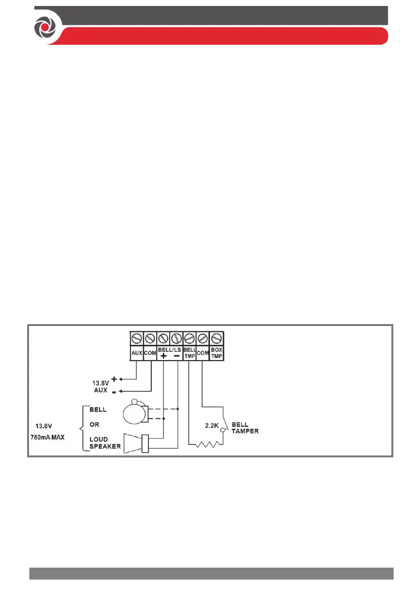
Connecting the Bell / Loudspeaker
The Bell & LS (loudspeaker) terminals provide power to the internal bell (siren).
NOTE: A maximum of 750 mA may be drawn from this output.
To connect the internal bell (siren):
1. With main panel power removed, connect the internal bell with the correct
polarity (for installation instructions see the packaged installation instructions).
2. At SW1 on the main panel PCB, be sure to position the BELL DIP switch
correctly accordingly (regarding bypassing or not bypassing the bell tamper).
See Main Panel DIP Switch Settings, page 27.
IMPORTANT: To avoid bell loop trouble, if no connections are made to an internal
bell, on the terminal block install a provided 2.2K Ω resistor to the BELL/LS
(+ and – ) screw terminals, unless fitting an extension speaker with DIP switch 1 in
the OFF position.
Connecting the Bell Tamper
To utilize the bell tamper:
• With main panel power removed, connect the bell tamper to the BELL TMP
and COM terminals on the main panel using a 2.2K Ω resistor in serial.
BELL/LS (+): To connect to the
self-activated bell’s (SAB)
positive hold off input.
BELL/LS (—): To connect to the
SAB negative hold off input.
BELL TMP: To connect to the
bell input of the SAB Unit.
To not utilize the bell tamper:
• If the installation does not utilize the main panel’s bell tamper, on the main
panel PCB set DIP switch 5 to ON to bypass the tamper protection. See Main
Panel DIP Switch Settings, page 27 .
IMPORTANT: Even if you don’t utilize the bell tamper, connect a provided
2.2K Ω resistor between the BELL TMP and COM terminals.