11
2017 Page 34 5IN2413 B
Connecting the Box Tamper (Wall Tamper)
The box tamper is pre-installed on the main panel housing (see box/enclosure
instructions).
To utilize the box tamper:
1. Connect back tamper wires to the BOX TMP terminals on the terminal block, or
alternatively connect via cable to the BOX TMP connection jack on the PCB.
NOTE: Do not wire the box tamper to both the terminal block and the PCB
connector simultaneously.
2. Set the box tamper DIP switch (DIP Switch 4) on main panel PCB to OFF
(see Main Panel DIP Switch Settings, page 27).
To not utilize the box tamper:
• If not utilizing the main panel’s box tamper, to bypass tamper protection set
DIP switch 4 on panel PCB to ON (see Main Panel DIP Switch Settings, page 27).
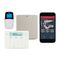
Connecting 4-Wire Smoke Detectors
ProSYS Plus supports 4-wire smoke detectors. Refer to the detector’s packaged
installation instructions.
• To connect a 4-wire smoke detector or device that requires resetting after an
alarm condition, connect the auxiliary power
AUX and output terminals. Use a
power supervision relay to supervise the 4-wire smoke detectors. Loss of
power to the detector(s) de-energizes the relay, causing a break in the zone
wiring and a “Fire Fault” message at the panel. Remember to define the output
as Switched Auxiliary.
• In addition, when connecting a 4-wire smoke detector, observe the wiring
guidelines mentioned in the previous sections, along with any local
requirements applicable to smoke detectors, as per the following diagram: