Section 04 FUEL SYSTEM
Subsection 02 (FUEL TANK AND FUEL PUMP)
GENERAL
WARNING
Fuel lines remain under pressure at all times.
Always proceed with care and use appro-
priate safety equipment when working on a
pressurized fuel system. Wear safety glasses.
WARNING
Always disconnect battery prior to work-
ing on the fuel system. Fuel vapors are
flammable and explosive under certain con-
ditions. Always work in a well ventilated
area. Do not allow fuel to spill on hot en-
gine parts and/or on electrical connectors.
Proceed with care when removing/installing
high pressure test equipment or disconnect-
ing fuel line connections. Cover the fuel
line connection with an absorbent shop rag.
Wipe off any fuel spillage in the bilge.
WARNING
When the repair is completed, ensure that
hoses and connections from fuel rail to the
fuel pump are properly secured. Then, pres-
surize the fuel system. After carrying out a
fuel pump pressure test, use the valve on the
fuel pressure gauge to release the pressure
(if so equipped).
WARNING
The fuel pump is energized for a few seconds
each time the START button is depressed.
It builds fuel system pressure very quickly.
Prior to pressing the START button, ensure
there are no disconnected or damaged fuel
lines that may leak fuel. A high pressure
leak test must be carried out whenever a fuel
system component has been disconnected.
WARNING
Ensure wires and hoses are routed and se-
cured away from any vibrating, rotating,
moving or hot components or sharp edges.
Use appropriate shields and fastening de-
vices as per factory standards.
NOTICE
Whenever repairing the fuel system,
always check for water infiltration in the fuel
tank. Replace any damaged, leaking or deteri-
orated fuel line.
SYSTEM DESCRIPTION
The fuel system is comprised of:
– A fuel tank
– A vented fuel tank cap
– A fuel pump module mounted inside the fuel
tank
– A variety of hoses.
The fuel pump module is basically comprised of:
– An electric fuel pump mounted inside a canister
type pump reservoir
– A lower inlet filter
– An upper outlet filter
– A pressure regulator
– A float type fuel level sensor.
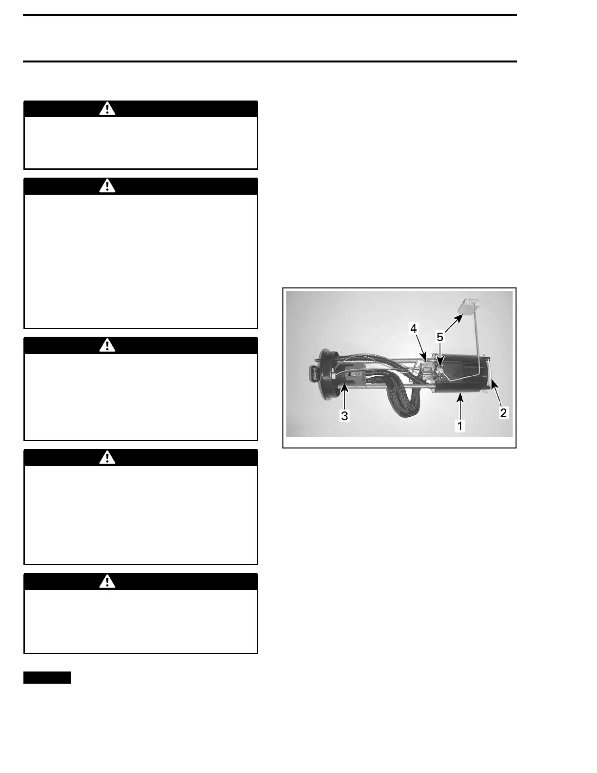
smr2008-022-007_a
FUEL PUMP MODULE
1. Fuel pump reservoir
2. Lower inlet f ilter
3. Upper outlet filter
4. Fuel pressure regulator
5. Float type fuel level sensor
Fuel Pump Operation
When the pump is in operation, it draws fuel into
the canister through a lower inlet filter and a disk
type valve.
The pressurized fuel is pushed through an upper
outlet filter to the fuel rail.
Excess fuel pressure generated by the pump is
routed from the upper filter back to the pump can-
ister reservoir by a pressure regulator mounted on
the pump reservoir cover.
When the START button is pressed, the electrical
system is powered. The fuel pump will come on
for approximately 2 seconds to pressurize the fuel
rail in preparation for the engine start.
The ECM supplies the ground signal to turn on the
fuel pump motor.
The pressure regulator will ensure appropriate
fuel pressure is supplied to the injectors.
90 219100893-021

 Loading...


