Section 06 STEERING AND PROPULSION
Subsection 01 (STEERING)
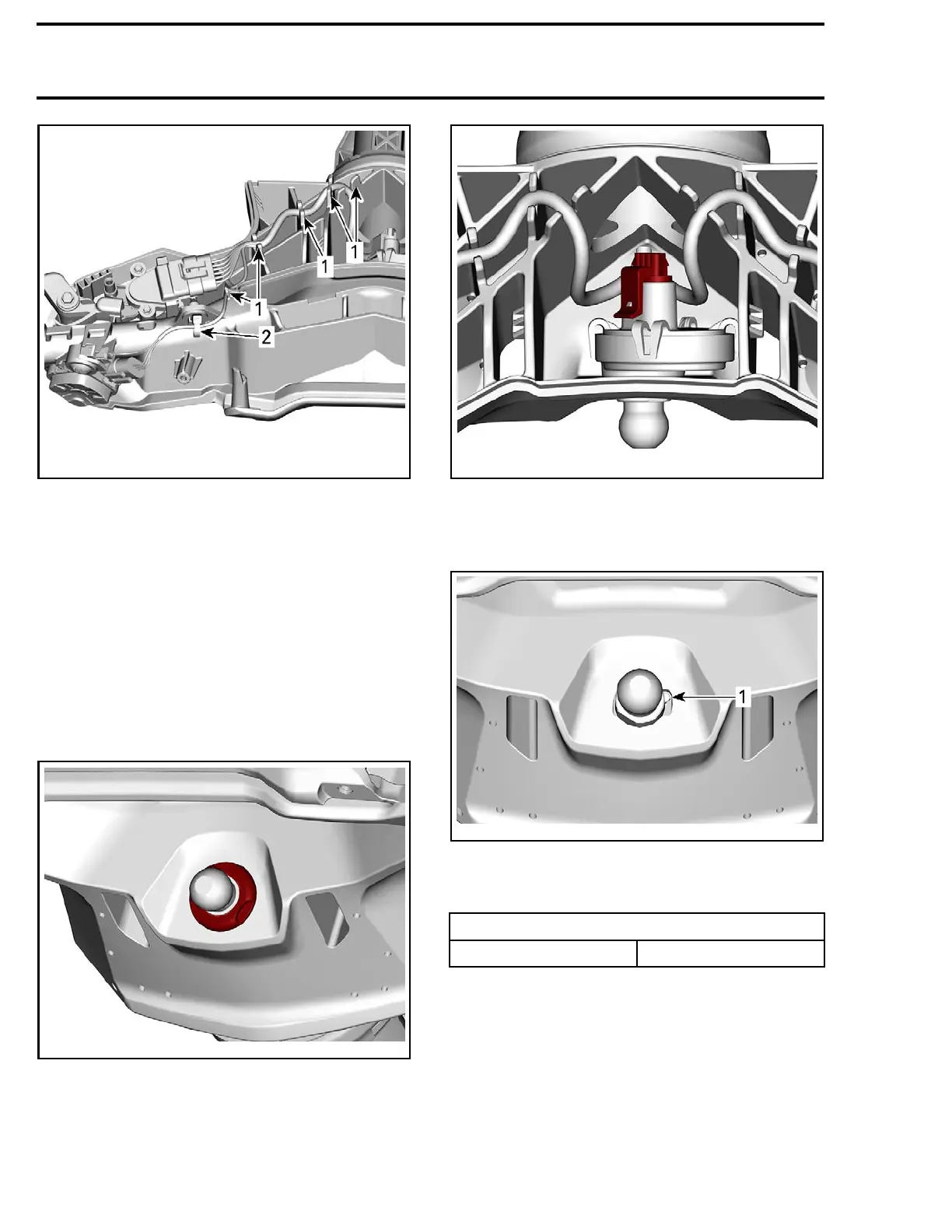
219100893-028-029_a
1. Harness slots
2. Locking tie
2. Clip the top of the cover.
3. Push both side of the cover to lock it with the
steering column.
4. Install switch covers.
REPLACING THE ENGINE
CUT-OFF SWITCH
Remove steering pad, see procedure in this sub-
section.
Remove cut-off switch nut.
219100893-028-009
Disconnect cut-off switch connector.
219100893-028-010_a
Push cut-off switch out of the steering column.
Install the engine cut-off switch b y aligning the
alignment pin into the notch of steering column.
219100
893-028-011_a
1. Alignment pin
Connect and install all removed parts using appro-
priate procedures.
TIGHTENING TORQUE
Engine cut-off switch n ut 2 N•m (18 lbf•in)
THROTTLE AND iBR LEVERS
NOTE: The following procedure demonstrates
the replacement of the throttle lever but the same
procedure will be used for the iBR lever.
Replacing the Lever
1. Remove
STEERING COVER
, see procedure in
this subsection.
156 219100963-017

 Loading...


