Section 06 ST EE RING AND PROPULSION
Subsection 02 (iBR, REVERSE AND VTS)
BRAKE AND REVERSE LEVER
SWITCH (BRLS)
Testing and Specifications
BRLS PINOUT
PIN SIGNAL
BRLS-A 5 VDC
BRLS-B GND
BRLS-C View signal % in BUDS2
BRLS-D 5VDC
BRLS-E GND
BRLS-F View signal % in BUDS2
NOTE: When moving BRLS lever, the BRLS per-
centage should increase or decrease in a steady
linear fashion.
If BUDS2 does not show BRLS percentage mov-
ing or if reading is erratic:
– Check for BRLS reference voltage.
– Check for BRLS ground.
– Carry out a continuity test of the w iring be-
tween the iBR actuator and the BRLS.
NOTE: When installed on vehicle the BRLS-C Vdc
signal should always be half of the BRLS-F Vdc
signal when testing with a multimeter.
To test, install Diagnostic harness between steer-
ing harness connectors.
REQUIRED TOOL
DIAGNOSTIC HARNESS
(P/N 529 036 384)
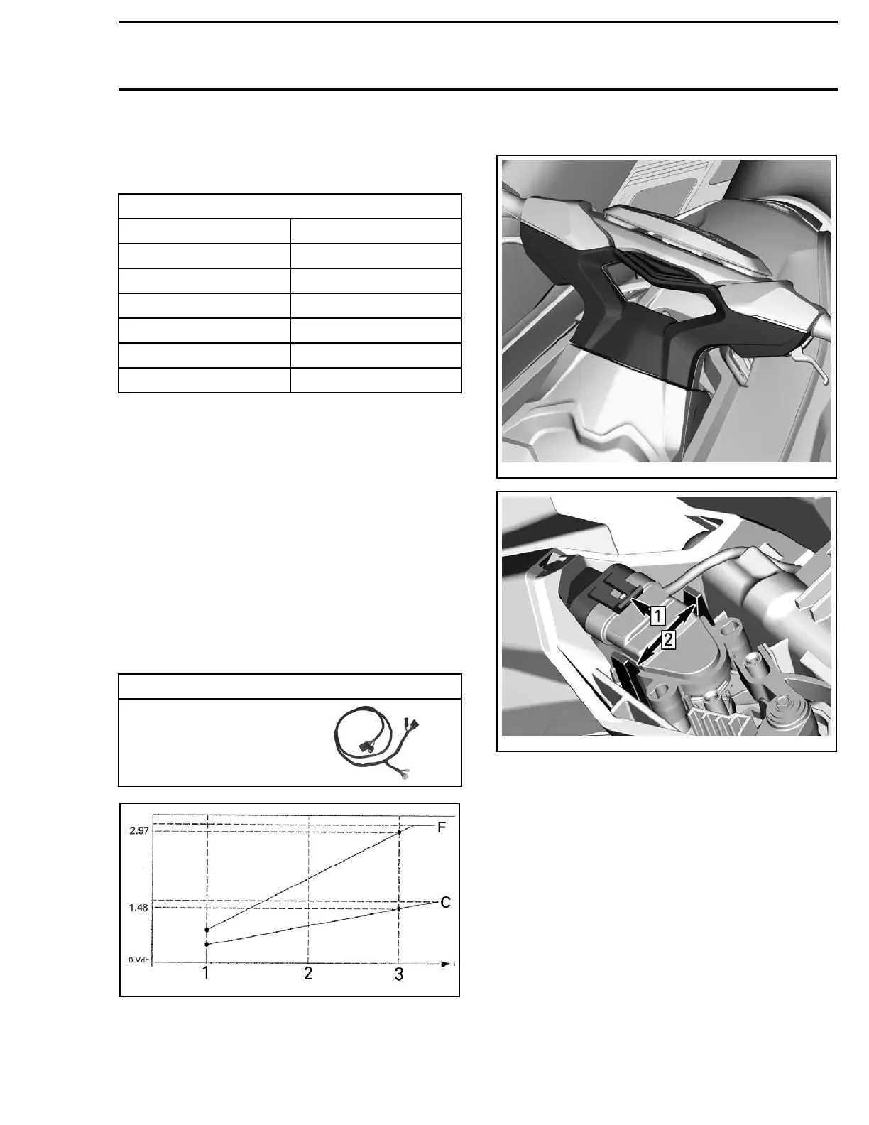
smr2014-119-017_a
APPROXIMATE BRLS SIGNAL VOLTAGE CURVE PINS F AND C
1. BRLS released
2. BRLS at 50% pulled
3. BRLS fully pulled
Removing the BRLS
219100893-029-019_a
smr2014-119-013_a
Installing the BRLS
The installation is the reverse of the removal pro-
cedure.
219100963-018 181

 Loading...


