Section 02 ENGINE
Subsection 03 (EXHAUST SYSTEM)
NOTICE
The engine must not run more than
30 seconds without water supply. Stopping en-
gine might be necessary.
Ensure water flows out of jet pump while flushing.
NOTICE
Never run engine longer than 2 min-
utes. Drive line seal has no cooling when wa-
tercraft is out of water.
Close the water tap.
Remove the garden hose from the vehicle.
Quickly rev the engine 3-5 times at approximately
5000 RPM.
Stop engine.
NOTICE
Always close the water tap before
stopping the engine.
NOTICE
Remove quick connect adapter after
flushing operation (if used).
PROCEDURES
EXHAUST MANIFOLD
RTX1503ACEMY18-001-002_a
TYPICAL
Removing the Exhaust Manifold
1. Move muff
ler rearwards to make room. Refer
to
REMOV
ING THE MUFFLER
in this subsec-
tion.
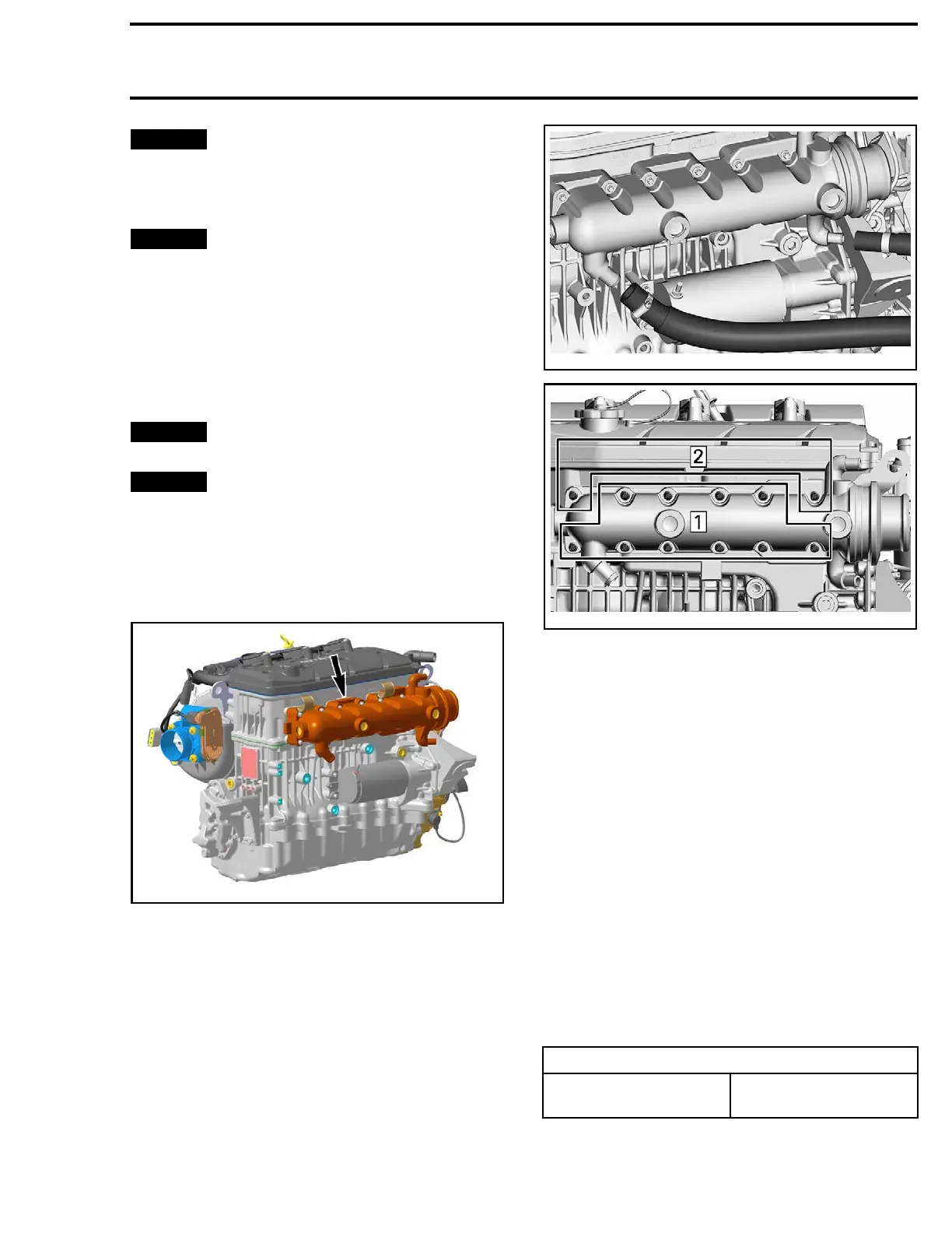
smr2016-012-007
smr2016-012-008_b
Step 1: R
emove first
Step 2: Remove last
2. Remove the exhaust manifold from vehicle.
Inspect
ing the Exhaust Manifold
Inspect exhaust manifold condition paying atten-
tion for cracks or other damage. Check contact
surfaces and hose. Replace any defective part.
Inspect plane surfaces for warpage. Small defor-
mation can be corrected by grinding surface with
a fine sand paper. Install sand paper on a surface
plate and rub part against oiled sand paper.
Clean a
ll metal components in a solvent.
Installing the Exhaust Manifold
The ins
tallation is the reverse of the removal pro-
cedure
. However, pay attention to the following.
NOTE: There is no gasket between cylinder block
and exhaus t manifold.
Apply threadlocker on threads of screws.
SERVICE PRODUCT
Exhau
st manifold screws
LOCTITE 243 (BLUE)
(P/N 293 800 060)
219100893-012 37

 Loading...


