Section 05 ELECTRICA L SYSTEM
Subsection 02 (WIRING HARNESS AND CONNECTORS)
smr2009-045-028_a
NOTICE
Before installing terminals in the
connectors, ensure all terminals are properly
crimped on the wires. After installation of the
wire terminals in the connectors, ensure they
are properly locked by gently pushing on them
as if to extract them.
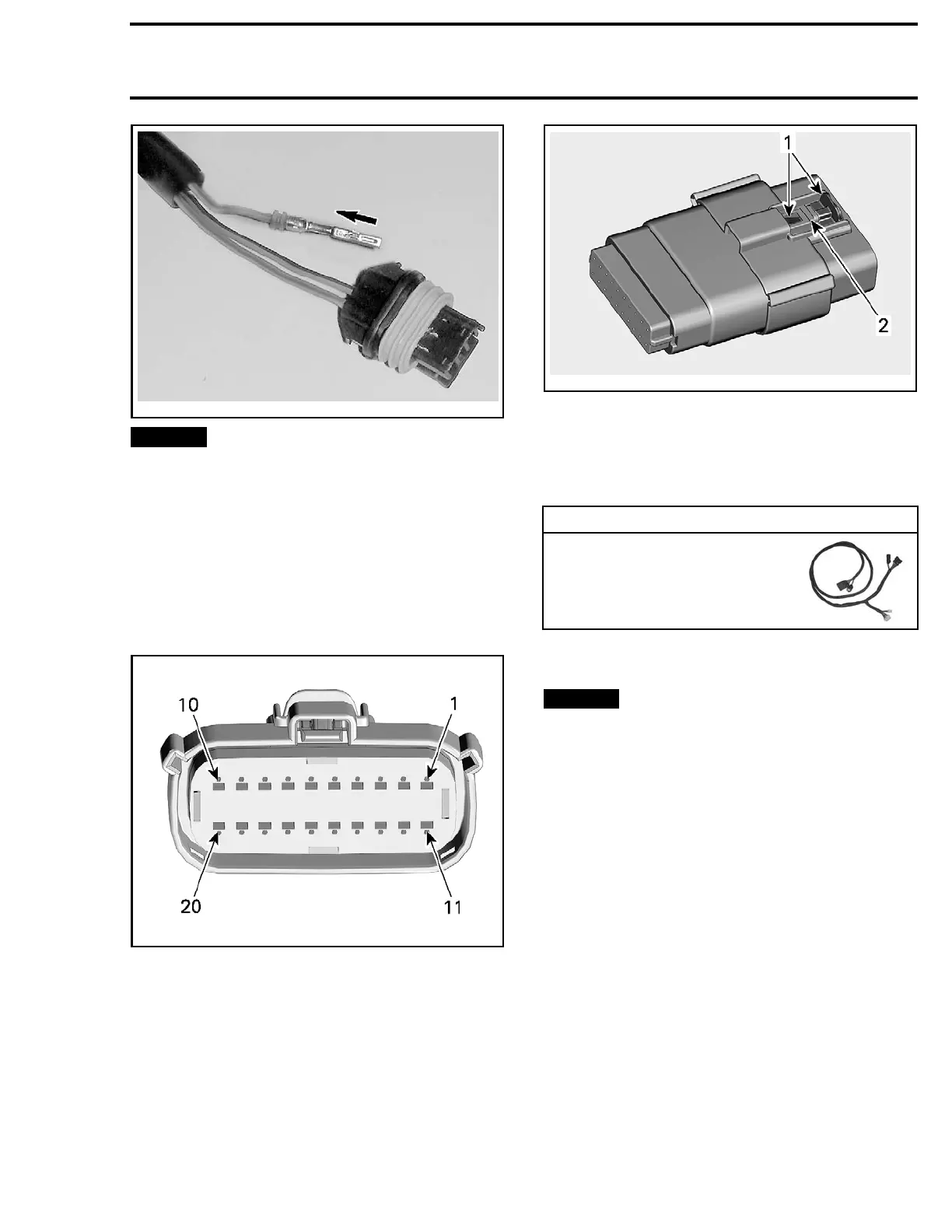
ACC, HIC, HIC1,HIC2, USB
IC,(MOLEX)
NOTE: 20 pin Molex is shown
smr2014-030-012_a
1. Female connector pin-out (sockets)
Disco
nnecting the Connector
Pull back the red secondary lock from the connec-
tor latch lever. Do not remove it from the latch.
Push the two connector assemblies together to
unload the latch.
Depr
ess the latch lever and pull the two connector
asse
mblies apart.
smr2014-045-003_a
1. Red secondary lock (shown out)
2. Latch lever
Probing the Connector
1. Disconnect the steering connector in the vehi-
cle and connect it to the diagnostic harness.
REQUIRED T
OOL
DIAGNOSTIC HARNESS
(P/N 529 036 384)
2. Probe th
e applicable circuit u sing the test con-
nector o
n the diagnostic harness.
NOTICE
Attempting to probe the connector
without using the diagnostic connector may
damage the connector pins, or even cause a
short circuit if testing an energized circuit.
Extracting the Socket (Female
Connector)
1. Insert
a small flat screwdriver in the pry holes
of the
socket locator, on the socket side of the
conne
ctor.
219100963-012 117

 Loading...


