Section 05 ELECTRICA L SYSTEM
Subsection 03 (CHARGING SYSTEM)
3. Defective charging system wiring or connec-
tions.
- Check for damaged wiring.
- Check for damaged or loose connections.
REPETITIVE BLOWN F6 FUSE
1. Voltage regulator/rectifier internal circuit
shorted to ground.
- Refer to TESTING VOLTAGE REGULATOR/REC-
TIFIER FOR BLOWN F6 FUSE in this subsection.
PROCEDURES
VOLTAGE
REGULATOR/RECTIFIER
Testing the Voltage
Regulator Continuity
Due to internal circuitry, there is no static test
available to check continuity.
Voltage Regulator/Rectifier Location
219100893-024-001
Testing Voltage Regulator/Rectifier for
Blown F6
Fuse
1. Detach the voltage regulator/rectifier from sup-
port. Refer to
REMOVING THE VOLTAGE REG-
ULATOR/RECTIFIER
in this subsection.
2. Disconnect the voltage regulator/rectifier
2-wire connector.
3. Insta
ll a new fuse.
If the fuse still burns, check for a shorted wire or
connector pin.
If fuse does not burn, replace regulator/rectifier.
Removing the Voltage
Regulator/Rectifier
1. Disconnect both connectors from the voltage
regulator/rectifier.
219100893
-024-002
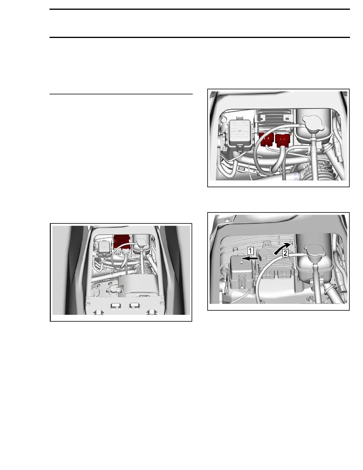
2. Push the support locking tab and remove volt-
age regulator/rectifier from its support.
21910
0893-024-003_a
Step 1: Push locking tab
Step 2: Tilt voltage regulator to re move
Inst
alling the Voltage
Regulator/Rectifier
Installation is the reverse of the removal proce-
dure.
219100963-013 125

 Loading...


