Section 06 STEERING AND PROPULSION
Subsection 04 (DRIVE SHAFT)
PROCEDURES
DRIVE SHAFT
Drive Shaft Ac
cess
Remove the seat and engine service cover. Refer
to
BODY
subsection.
Removing the D
rive Shaft
Procedures
NOTE: Ensure jet pump is installed before begin-
ning this procedure.
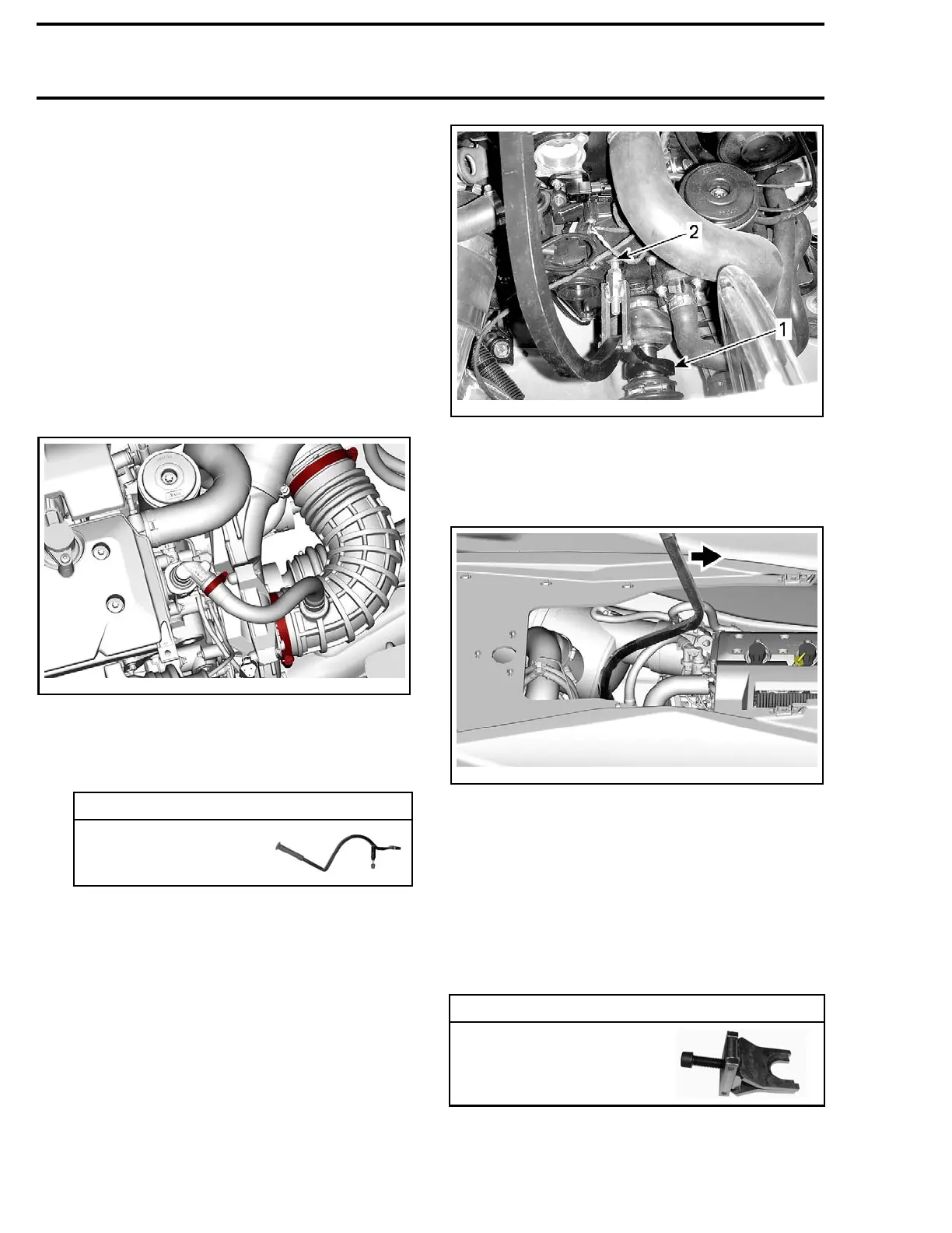
1. On supercharg
ed engines, remove air intake
hose.
219100893-031-001
2. Lift rubb
er protector to expose PTO seal as-
sembly.
3. Confirm the floating ring is not stuck on drive
shaft as follows:
REQUIRED TOOL
DRIVE SHAFT
C-CLIP REMOVER
(P/N 529
036 026)
3.1 Place the fork of drive shaft C-clip remover
against floating ring.
3.2 Place the adjustable arm against the en-
gine block or the supercharger.
smr2011-036-002_a
TYPICAL
1. Fork against floating ring
2. Adjustable arm
3.3 Move the tool handle toward the front of
vehicle to push floating ring rearward.
219100893-031-003_a
The next steps (4 to 12) should be performed only
if the floating ring seems stuck or hard to move.
Otherwise, go to the step 13.
NOTE: Do not remove circlip at this time.
4. Remov
e the drive shaft C-clip remover.
5. If equipped, remove the supercharger. Refer to
SUPERCHARGER
subsection.
6. Install the following tool on drive shaft with its
largest opening on PTO s ide.
REQUIRED TOOL
FLOA
TING RING
TOOL (TYPE II)
(P/N 529 036 116)
202 219100963-020

 Loading...


