Section 03 ELECTRONIC MANAGEMENT SYSTEMS
Subsection 01 (ENGINE MANAGEMENT SYSTEM)
GENERAL
SYSTEM DESCRIPTION
An engine management system (EMS) is used to
ensure a high power output with cleaner combus-
tion.
There are 6 mai
n systems that interact with the
engine manage
ment system:
1. Electronic fuel injection
2. D.E.S.S. System
3. Ignition Sys
tem
4. Starting System
5. T.O.P.S.
(Tip-Over Protection System)
6. iControl Sy
stem
Air management
The quantit
y of air admitted into the engine is cal-
culated by t
he throttle angle (TPS), the intake air
temperatur
e (IAT) and the manifold pressure/vac-
uum sensor
(MAP) on the intake manifold.
NOTE: the MAPTS combines the pressure and
temperature sensors into one sensor.
The operator's demands on the throttle lever are
captured by the throttle accelerator sensor (TAS)
and result in the movement of the electronic throt-
tle actuator (ETA).
Fuel management
The coolant temperature sensor (CTS) is used
to determine engine temperature. The ECM will
slightly lean out the fuel mixture to bring a cold
engine to operating temperature faster. Once the
engine is at operating temperature, this stops.
NOTE: On s
ome engines the oil temperature sen-
sor is als
o used to calculate engine temperature.
In response to changes in air management, the
ECM will adjust the quantity of fuel injected to op-
timize combustion.
The ECM will vary injection duration and timing to
minimize emissions and maximize power.
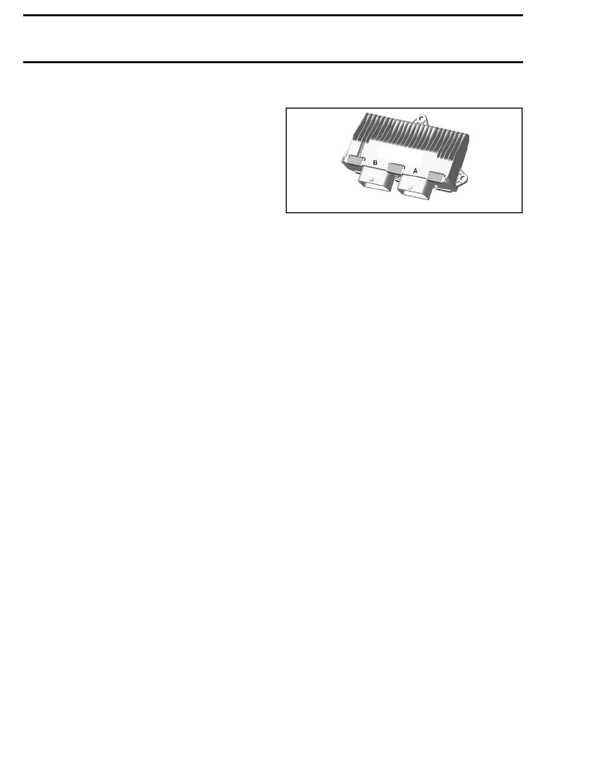
Engine Control Module (ECM)
smr2009-027-005
ECM
The ECM is the main component of the engine
management system. It controls the electrical
system and the engine management functions by
processing the information obtained from various
switches, controls and sensors that it compares
to predetermined parameters stored in the ECM.
It also inte
racts with the other electronic systems
through th
e CAN bus (information center and
iControl S
ystem) for various functions that affect
engine man
agement.
It features a permanent memory that will store
fault codes, customer information and other
engine information, even when the battery is
removed from the vehicle.
The ECM controls the following engine manage-
ment functions:
Engine RP
M Limiter
The ECM limits maximum engine speed. It moni-
tors engine RPM through the CPS and varies fuel
injection, ignition and throttle plate opening as
necessary.
Engine Speed Control
The ECM co
ntrols the engine idle RPM. In addi-
tion, it c
an vary the engine speed by command-
ing the e
lectronic throttle actuator (ETA) to open or
close ba
sed on throttle position and various other
inputs.
The ETA also allows for other functions of
the iCon
trol system.
Monitoring System
The ECM monitors:
– The electrical and electronic components of the
engine system
– The iCo
ntrol system
– The information center (gauge)
– Some components of the electrical system
– Signal
s from other electronic modules
For more information, refer to
DIAGNOSTIC AND
FAULT CODES.
64 219100963-009

 Loading...


