Section 06 STEERING AND PROPULSION
Subsection 02 (iBR, REVERSE AND VTS)
GENERAL
During assembly/installation, use torque values
and service products as indicated in the exploded
view.
Clean threads
before applying a threadlocker. Re-
fer to
SELF-LO
CKING FA S TENERS
and
LOCTITE
APPLICATION
a
t the beginning of this manual for
complete pro
cedure.
WARNING
Torque wrench tightening specifications
must be strictly adhered to.
Locking devices (e.g.: locking tabs, elastic
stop nuts, self-locking fasteners, cotter pins,
etc.) must be replaced with new ones.
Hoses, cables or locking ties removed during a
procedure must be reinstalled as per factory stan-
dards.
SYSTEM DESCRIPTION (iBR)
iBR System Components
219100893-029-001_a
TYPICAL
1. Actuat
or
2. Air chamber
3. iBR nut
4. Actua
tor shaft
5. Connecting arm
6. Connecting arm bellows
7. iBR Re
verse Gate
219100893-029-002_a
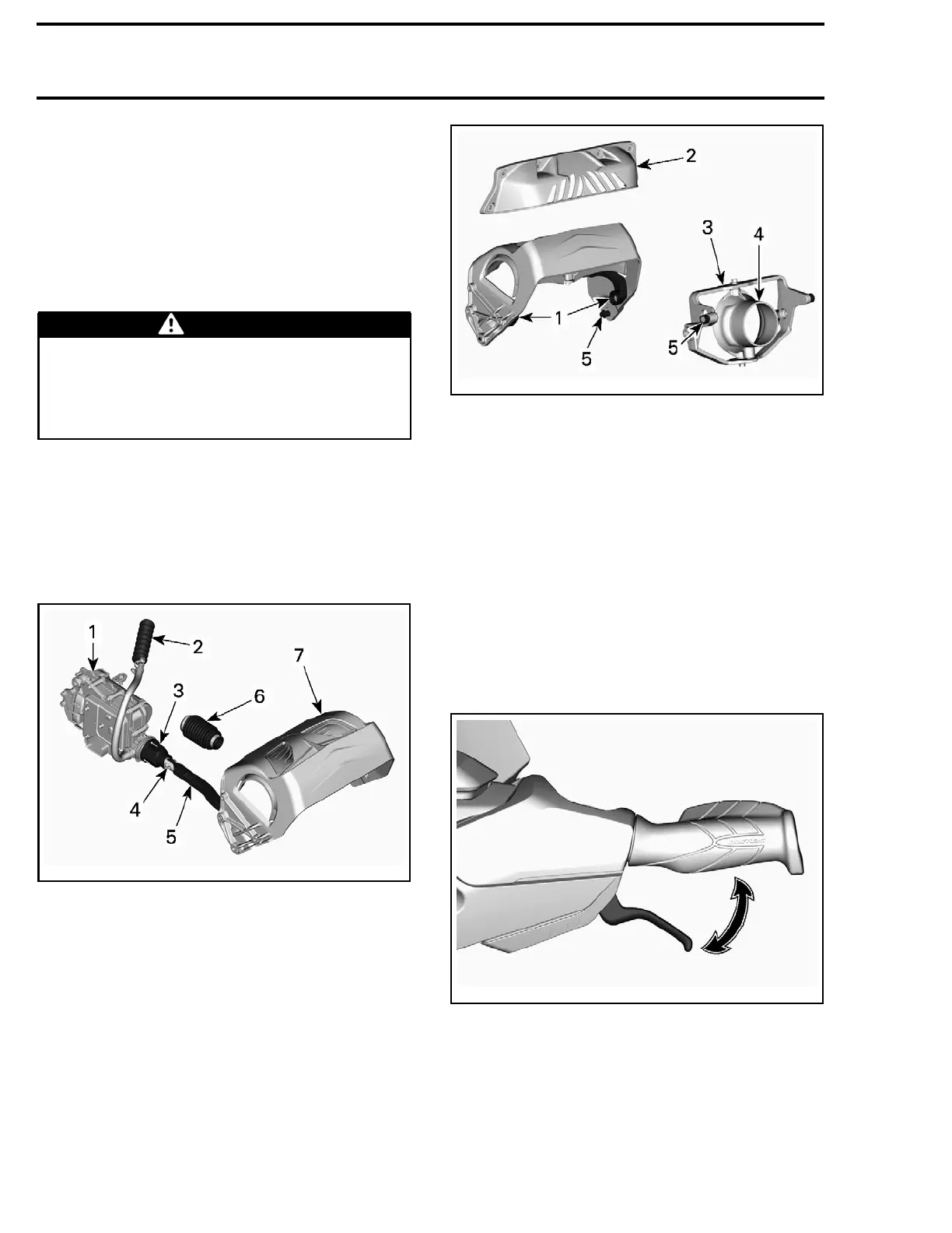
1. Support plates
2. Protective guard
3. VTS trim
4. Nozzle
5. Friction sleeves
The iBR (intelligent Brake and Reverse) is an elec-
tronically controlled braking and reverse system.
The iBR module controls the position of the iBR
gate to provide forward thrust, reverse thrust,
braking thrust, and neutral.
The operator commands the position of the iBR
gate using either the throttle lever for forward
thrust, or the iBR lever for neutral, reverse, and
for the braking function.
The iBR lever is located on the LH side of the han-
dlebar.
219100893-029-005_a
When t
he iBR lever is pulled in, it operates the
brake
and reverse lever sensor (BRLS). It is a dou-
ble ou
tput hall effect sensor. The redundancy is
used
for security purposes.
The BRLS sends the signals to the iBR module.
The iBR module controls an electric motor that in
turn raises or lowers the iBR gate through a me-
chanical drive unit.
168 219100963-018

 Loading...


