Section 06 STEERING AND PROPULSION
Subsection 01 (STEERING)
On all models
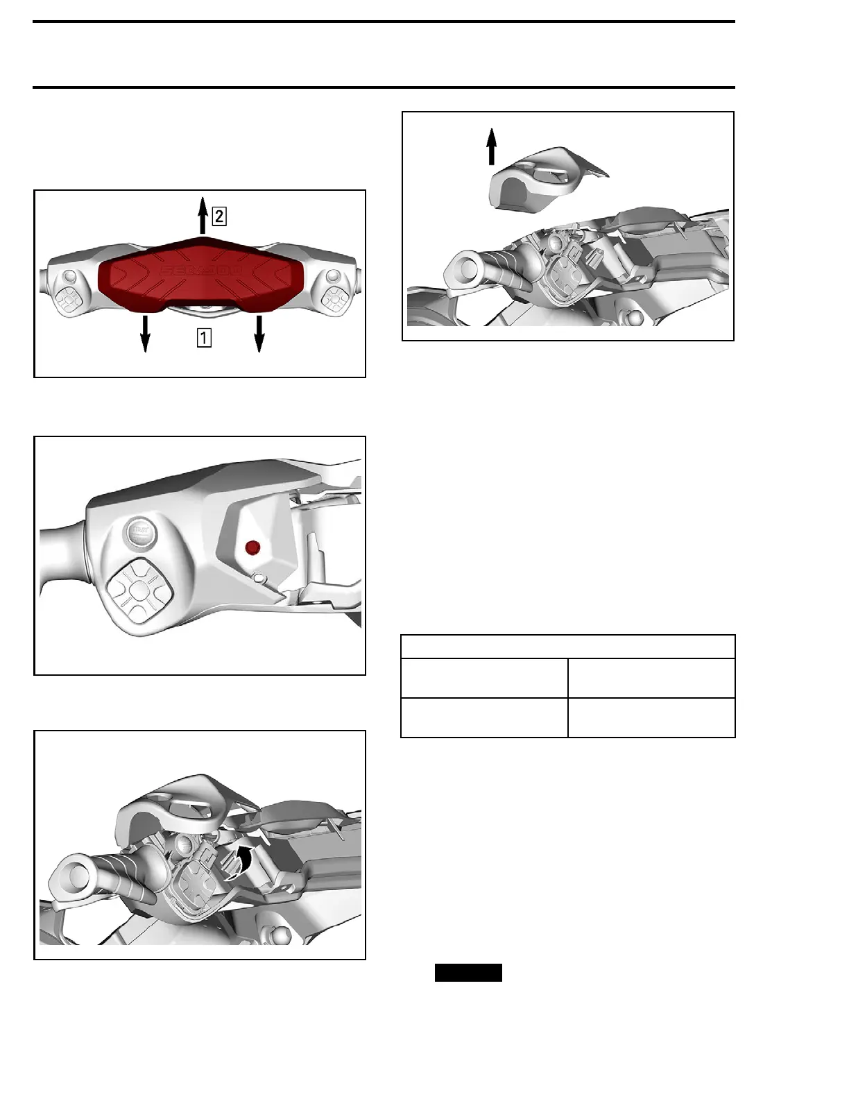
2. Remove steering pad by pulling the bottom first
and then the top.
219100893-028-005_a
TYPICAL
3. Remove the
switch cover retaining screw.
219100893-028-006
LH SIDE SHOWN
4. Remove
the switch cover.
219100893-028-301_a
219100893-028-302_a
Installing the Handlebar Switch Cover
(LH or RH)
Installation is the reverse of the removal proce-
dure. However, pay attention to the following.
1. Route wires to avoid pinching them.
2. Position the switch cover onto the steering
cover.
3. Ensure positioning of steering electrical har-
ness.
4. Ensure proper engagement of the upper hous-
ing and cover tabs.
5. Ensure proper engagement of upper and lower
switch covers.
6. Tighten housing cover screw to specification.
TIGHTEN
ING TORQUE
Housing cover screw
2.5 N•m ± 0.5 N•m
(22 lbf
•in ±4lbf•in)
Steering p ad retaining
screw (
RXT- X)
5.5 N•m ± 0.5 N•m
(49 lbf•in ±4lbf•in)
STEERING COVER
Removing the Steering Cover
1. Remove steering pad and both handlebar
switch covers. See procedure in this subsec-
tion.
2. Unloc
k steering cover from steering.
2.1 Insert a small tool, such as a small flat
screwdriver, into a steering cover hole.
Press the tool against the retaining tab to
unlock it. Repeat for the other side.
NOTICE
The t
ool must be inserted per-
fect
ly straight to avoid breaking the tab
hold
er.
154 219100963-017

 Loading...


