Section 05 ELECTRICAL SYSTEM
Subsection 02 (WIRING HARNESS AND CONNECTORS)
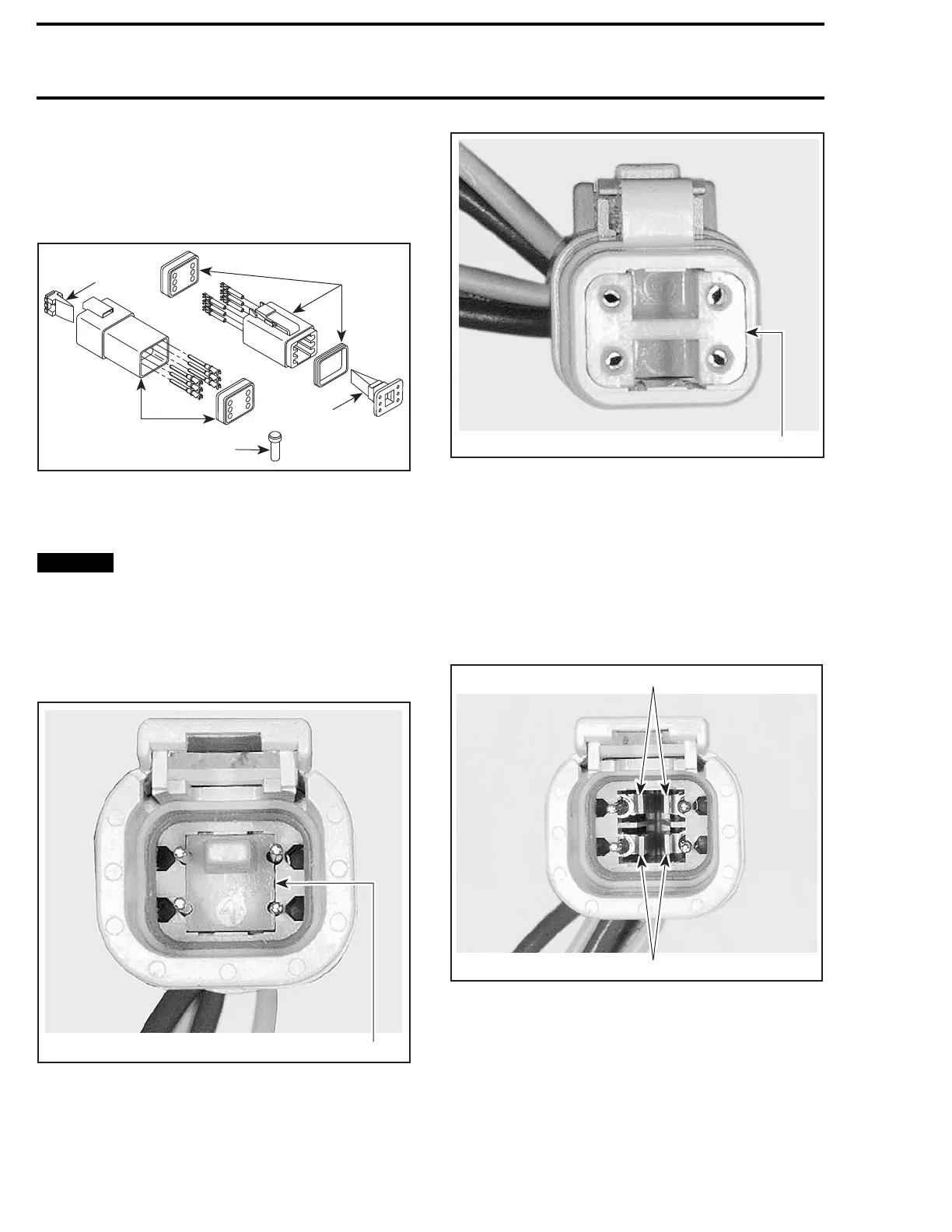
DIAGNOSTIC CONNECTOR, LTS
(DEUTSCH)
Disassembling and reassembling the
Connector
F00H1CA
1
3
4
2
3
TYPICAL - DEUTSCH CONNECTOR
1. Male connector
2. Female connector
3. Secondary lock
4. Sealing cap
NOTICE
Do not apply dielectric grease on ter-
minal inside connector.
To remove terminals from connector, proceed as
follows:
1. Using long nose pliers, pull out the plastic lock
from between the terminals.
1
V01G0OA
TYPICAL - FEMALE CONNECTOR
1. Female lock
V01G0PA
1
TYPICAL - MALE CONNECTOR
1. Male lock
NOTE: Before pin extraction, push wire forward
to relieve pressure on retaining tab.
2. Insert a 4.8 mm (.189 in) wide screwdriver
blade inside the front of the terminal cavity.
3. Pry the retaining tab away from the terminal
while gently pulling the wire and terminal out
of the back of the connector.
V01G0QA
1
1
TYPI
CAL - FEMALE CONNECTOR
1. Retaining tabs
To install:
1. For insertion of a terminal, ensure the plastic
lock is removed.
2. Inse
rt terminal through the back of the connec-
tor
in the appropriate position, and push it in as
far
as it will go. You should feel or hear the ter-
min
al lock engage.
112 219100963-012

 Loading...


