Section 05 ELECTRICA L SYSTEM
Subsection 04 (STARTING SYSTEM)
Disconnect connector "B" from the ECM, refer to
WIRING HARNESS AND CONNECTOR
subsec-
tion.
Install ECM adapter tool on ECM harness connec-
tor "B".
Set the multimeter to
.
Press and hold the START/STOP switch and test
for continuity of the switch circuit as per following
table.
CONTINUITY TEST OF START/STOP SWITCH
CIRCUIT (BUT
TON PRESSED AND HELD)
FUSE BOX
ECM
CONNECTOR B
RESISTANCE
Pin E 3 B-H2
Closeto0
(continuity )
2. If the reading is as specified, the START/STOP
switch and its wiring are good.
3. If a high resistance or an open circuit is mea-
sured, carry out
TESTING THE START/STOP
SWITCH CONTINUITY
.
Testing the START/STOP Switch
Continuity
1. Remove START/STOP switch fuse (F10).
2. Disconnect the 20-pin steering harness connec-
tor:
219100893-025-001
1. 20-pin steering connector
3. Use the multimeter and select .
4. Measure resistance through switch as per fol-
lowing table.
CONTINUITY TES
TOFSTART/STOP
SWITCH CIRCUIT
SWITCH
POSITION
DIAGNOSTIC
HARNESS
CONNECTOR
RESISTANCE
Released
Infinite (OL)
Pressed and
held
Pins 1 and 4
Closeto0
If the switch does not test as specified, replace
the engine START/STOP switch.
If the switch tests as specified, check for an open
circuit between connections as per table:
OPEN CIRCUIT TEST
CIRCUIT CONNECTIONS RESISTANCE
Fuse box pin E3
Steering harness
connector pin 1
Steering
connector pin 4
ECM connector
B, pin H2
Must be close
to 0
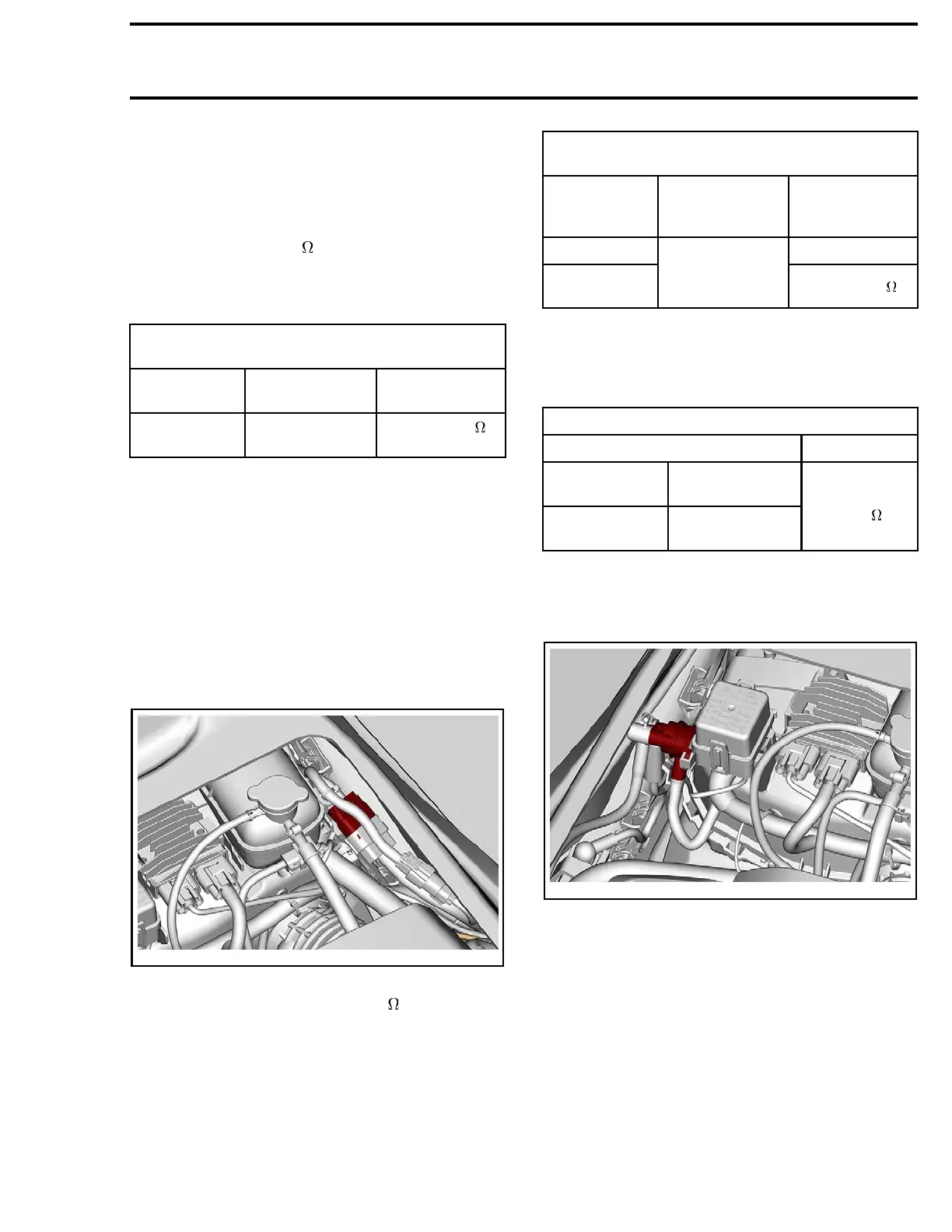
STARTER SOLENOID
Starter Solenoid Location
219100893-025-002
Testing Solenoid Input Voltage
1. Make sure F11 fuse is powered and in good
condition before testing.
2. Disconnect solenoid connector.
219100963-014 131

 Loading...


