Section 05 ELECTRICA L SYSTEM
Subsection 07 (ACCESSORIES)
ACCESSORIES
GENERAL
Refer to
WIRING DIAGRAM
subsection for diag-
nostic tips on troubleshooting electrical problems.
NOTE: The accessory c ircuit stays O N for a period
of up to 60 minutes after the engine is turned OFF
if the key remains on the D.E.S.S. post. If battery
voltage drops bellow 12.3V, the ECM will not al-
low the accessory circuit back ON until the engine
has been started.
WARNING
It is recommended to always disconnect the
battery when replacing any electrical compo-
nent. Always disconnect battery as specified,
BLACK (-) cable first. Do not place tools on
battery.
TROUBLESH
OOTING
DIAGNOSTI
CTIPS
IMPORTANT: When solving a n electrical problem,
the first thing to do is to check the battery condi-
tion as well as its cables and connections.
Install a battery charger on battery terminals for
any tests that involves a prolonged "key ON" pe-
riod. If battery voltage gets too low, not only test
results can be altered, but the vehicle electrical
system may not operate normally.
Pay atten
tion to ground wires. They could be-
come loos
e or corroded which causes them to
act as an
additional load in a circuit, dropping
voltage
and reducing current to components.
Some com
ponents may be grounded through
their ou
ter casing and mounted hardware. This
should a
lso be considered.
Electrical Connectors
Pay part
icular attention to ensure that pins are not
out of t
heir connectors, loose, or damaged. The
troubl
eshooting procedures may not cover prob-
lems re
sulting from one of these causes.
NOTICE
Ensure all terminals are properly
crimped on wires and connector housings are
properly fastened. When replacing any electric
or electronic part(s), always check electrical
connections. Make sure that they are clean,
corrosion-free, tight and make good contact.
The voltage and current might be too weak to
go through dirty or corroded connector pins
or terminals.
PROCEDURES
REMOVING AND INSTALLING
THE SOUND SYSTEM
Refer to
BODY
subsection.
PREREQUISITES OF SOUND
SYSTEM TESTS
Make sure diagnostic tool 1 fuse (F14) and cluster
fuse (F7) is in good condition and powered.
Make sure the battery is fully charged.
TESTING SOUND SYSTEM
GROUND WIRE CONTINUITY
1. Remove the c over. Refer to
BODY
subsection.
2. Disconnect the sound system connector.
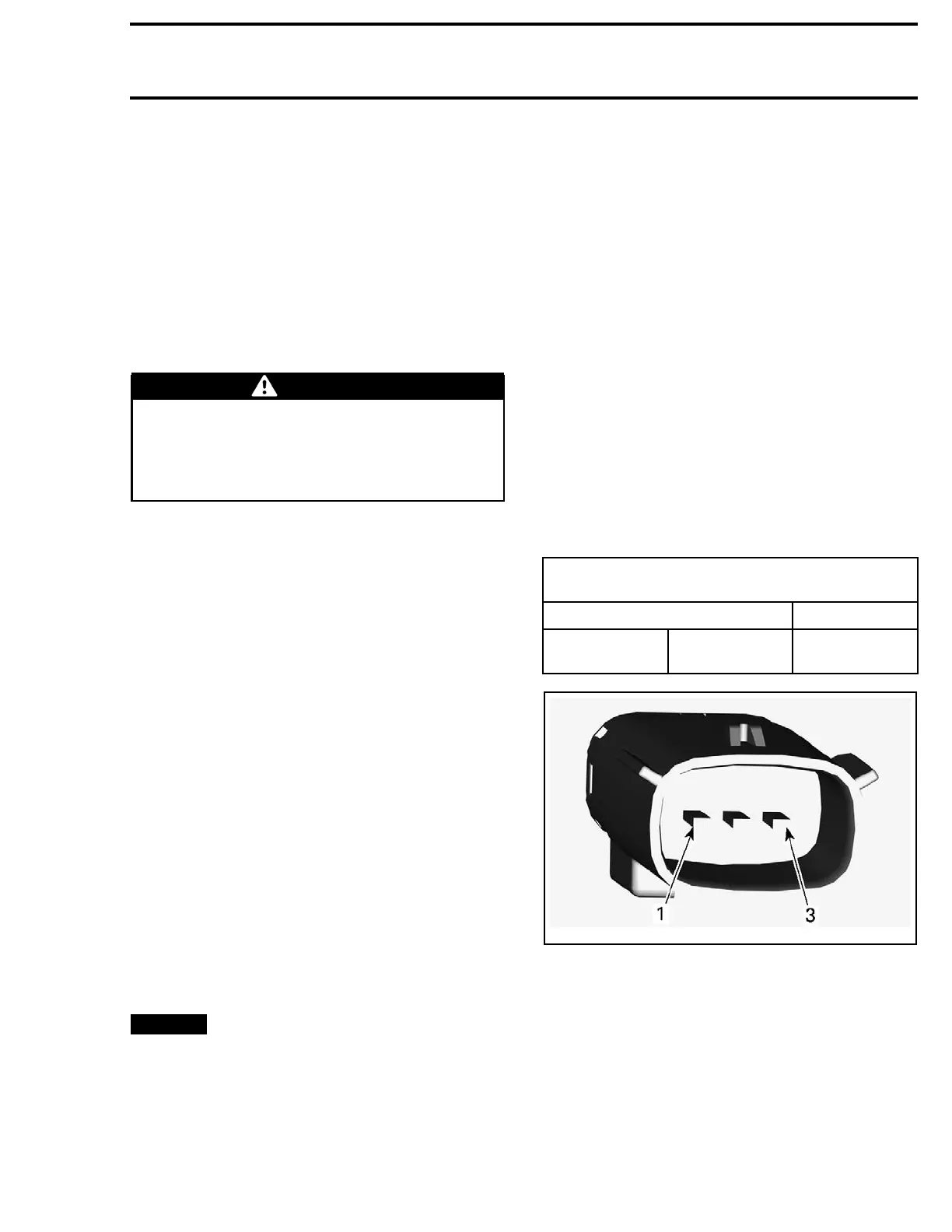
GROUND TEST AT SOUND SYSTEM
CONNECTOR
PROBE RESISTANCE
Pin 3 Battery -
Closeto0
Ohms
219100893-036-004_a
SOUND SYSTEM CONNECTOR PIN-OUT
If ground test is good, test the INPUT VOLTAGE.
TESTING SOUND SYSTEM
INPUT VOLTAGE
Press the START button and install the tether cord
on the engine cut-off switch.
219100963-016 145

 Loading...


