Section 04 FUEL SYSTEM
Subsection 01 (INTELLIGENT THROTTLE CONTROL (iTC))
2. Connect the diagnostic harness to make an
in-line connection between the disconnected
connectors.
REQUIRED TOOL
DIAGNOSTIC HARNESS
(P/N 529 036 384)
3. Install the tether cord on the engine cut-off
switch.
4.BrieflypresstheSTARTbuttontowakeupthe
ECM.
5. Measure th
e voltage readings on the installed
diagnosti
c harness connector as follows. Refer
to wiring d
iagram for details.
20-PIN CONNECTOR
IDLE
POSITION
WIDE OPEN
POSITION
PIN VOLTAGE (VDC)
13
(VI/BU)
14 (BK) 4.9 - 5.1
14 (BK)
15
(YL/BU)
0.15 - 0.35 1.4 - 1.6
16
(VI/GN)
17 (BK) 4.9 - 5.1
17 (BK)
18
(YL/GY)
0.4 - 0.6 2.9 - 3.1
If voltage is as per specification, the TAS sensor
is functional.
If voltage is out of specification, check continuity
of wires between the ECM and the sensor. If con-
tinuity is good, replace sensor.
6. Reins
tall removed components.
Replacing the TAS
Refer
to BRLS in iBR subsection.
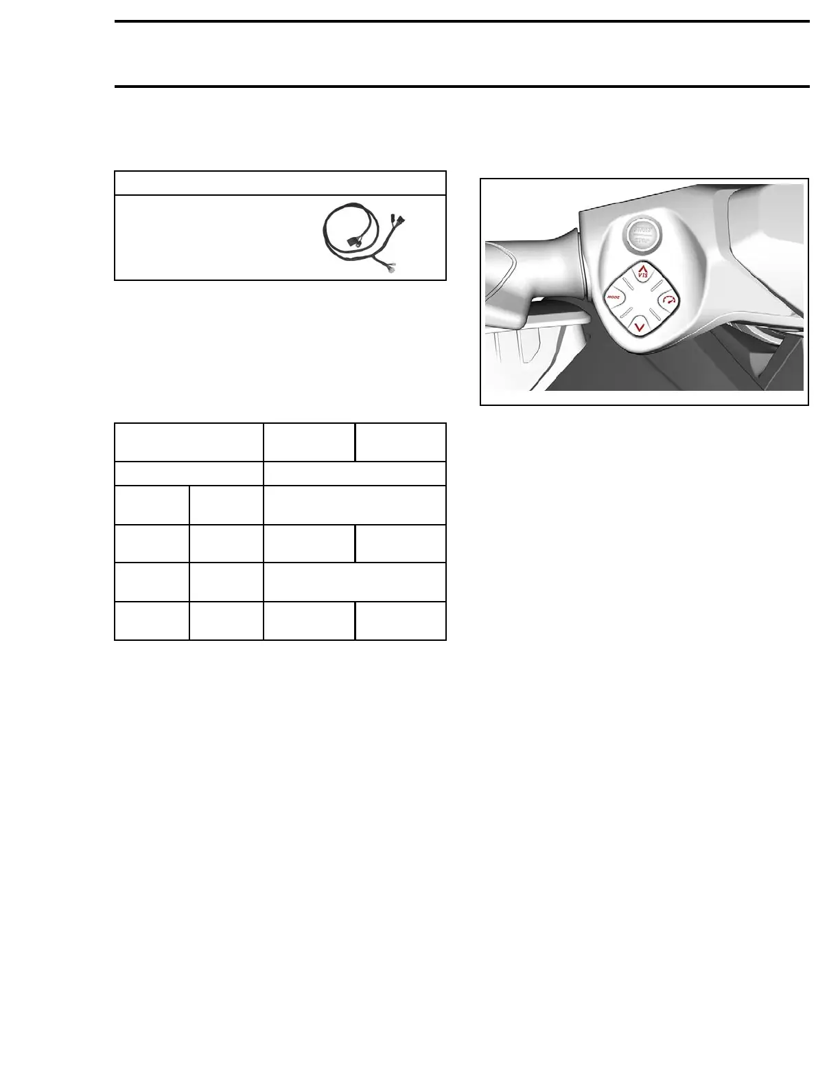
MODE/SPEED CONTROL SWITCH
Mode/Speed Control Switch Overview
219100963-011-001
The Mode/Speed Control switch contain a series
of 4 diodes for the Mode and Speed Control
switches.
The center wire to the switches (pin C), is com-
mon for Mode/Speed Control switch and VTS
switch. The other two wires (pins A and B), act
as signal wires for each set of switches to the
gauge. They actually each form one branch of an
electronic circuit within the gauge.
Each diode (in circuit) drops a nominal 0.6 Vdc
when conducting electricity. If the circuit current
passes through all four diodes (if the Mode/Speed
Control switch is open), a drop of 2.4 Vdc would
be measured across the 4 the diodes (pin A to
pin C). This 2.4 Vdc at p in A tells the gauge the
Mode/Speed Control switch is open.
If the Mode button is pressed, 2 diodes are by-
passed. The remaining two diodes in the circuit
drop 1.2 Vdc (at pin A).
If the Speed Control button is pressed, 1 diode
is bypassed. The remaining three diodes in the
circuit drop 1.8 Vdc (at pin A).
The gauge senses these voltages through pin 14
of its connector, and interprets them as signals
that tell it which switch is activated.
When Mode or Speed Control button is pressed,
a circuit within the gauge will translate it to CAN
protocol and transmit it through the CAN bus.
The ECM (engine control module) will react to the
command and carry out the function.
219100963-011 85

 Loading...


