Section 05 ELECTRICAL SYSTEM
Subsection 01 (POWER DISTRIBUTION AND GROUNDS)
NO. DESCRIPTION
F2
Through relay:
– Fuel pump
– Fuel injectors
– Ignition coils
15 A
F3
Through relay and F13:
– Blige Pum p
3A
F6
Direct power:
– Regulator/rec tifier
30 A
F7
Through rel
ay:
–Cluster
– Accessory connec tion
5A
F8
Through relay and F13:
– Depth Sounder
3A
F9
Direct power:
– iBR™ cont
rol
30A
F10
Direct power (through F12):
–START/STOP
5A
F11
Through r
elay:
–ECM
5A
F12
Direct power:
–Relay
–F10
–F14
30 A
F13
Through
relay:
–F3
–F8
–DiagTo
ol 2
15 A
F14
Direct power (through F12):
–DiagTool1
15 A
Note 3: If equipped.
RELAY
Relay Pin Identification
The relay is in the fuse box. Refer to
FUSE BOX
.
RELAY PIN IDENTIFICATION
FUNCTION FUSE BOX PIN CONDITION
12-volt in put at
winding
B6
Direct battery
power
from fuse F12
Control
B4
Grounded
by ECM B
pin H2 once
START/STOP
is depressed
12-volt in put at
contacts
A6
Direct battery
power
from fuse F12
12-volt output A4
-
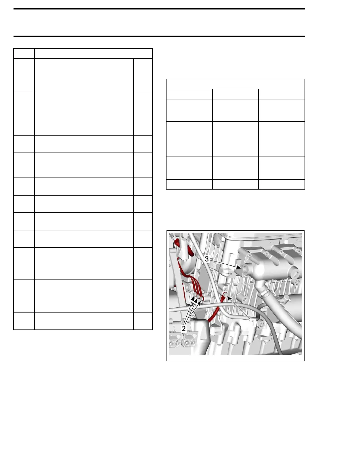
GROUNDS
All the ground terminals a re located on the front
of engine.
219100893-022-004_a
FRONT OF ENGINE
1. Battery ground
2. Electrical components grounds
3. Exhaust manifold
106
219100893-022

 Loading...


