Section 03 ELECTRONIC MANAGEMENT SYSTEMS
Subsection 04 (COMMUNICATION TOOLS)
COMMUNICATION TOOLS
SERVICE TOOLS
Description Part Number Page
DIAGNOSTIC CABLE ....................... ............................................. 710 000 851 ........................................... 71
MPI-2 INTE RFACE CARD .............. ............... .............................. ... 529 036 018 ........................................... 71
MPI-3 INTE RFACE CARD .............. ............... .............................. ... 529 036 353 ........................................... 71
GENERAL
Refer to the B.U.D.S. directory on
KNOWLEDGE
CENTER
for all BUDS2 related information, includ-
ing:
– Download link
– User manual (programming keys, reading fault
codes, writing data to modules etc.)
– Installation instructions
DownloadandinstallthesoftwareonaPC.
Connect the vehicle to the BRP diagnostic soft-
ware (BUDS2).
REQUIRED TOOLS
MANDATORY TOOLS
A personal computer (laptop or desktop)
MPI-2 INTERFACE CARD
(P/N 529 036 018)
OR
MPI-3 INTERFACE CARD (P/N 529
036 353)
DIAGNOSTIC CABLE
(P/N 710 000 851)
OPTIONAL TOOL
Extension cable
available at electronic retail outlets.
Do not exceed 7.5 m (25 ft)
Multi-Purpos
e Interface Card (MPI-2 or
MPI-3)
The Multi-Purpose Interface (MPI) in conjunction
with the diagnostic cable is used with BUDS2
to communicate with the engine control module
(ECM) and other modules.
The MPI card us
es the power from the PC com-
puter's USB p
ort.
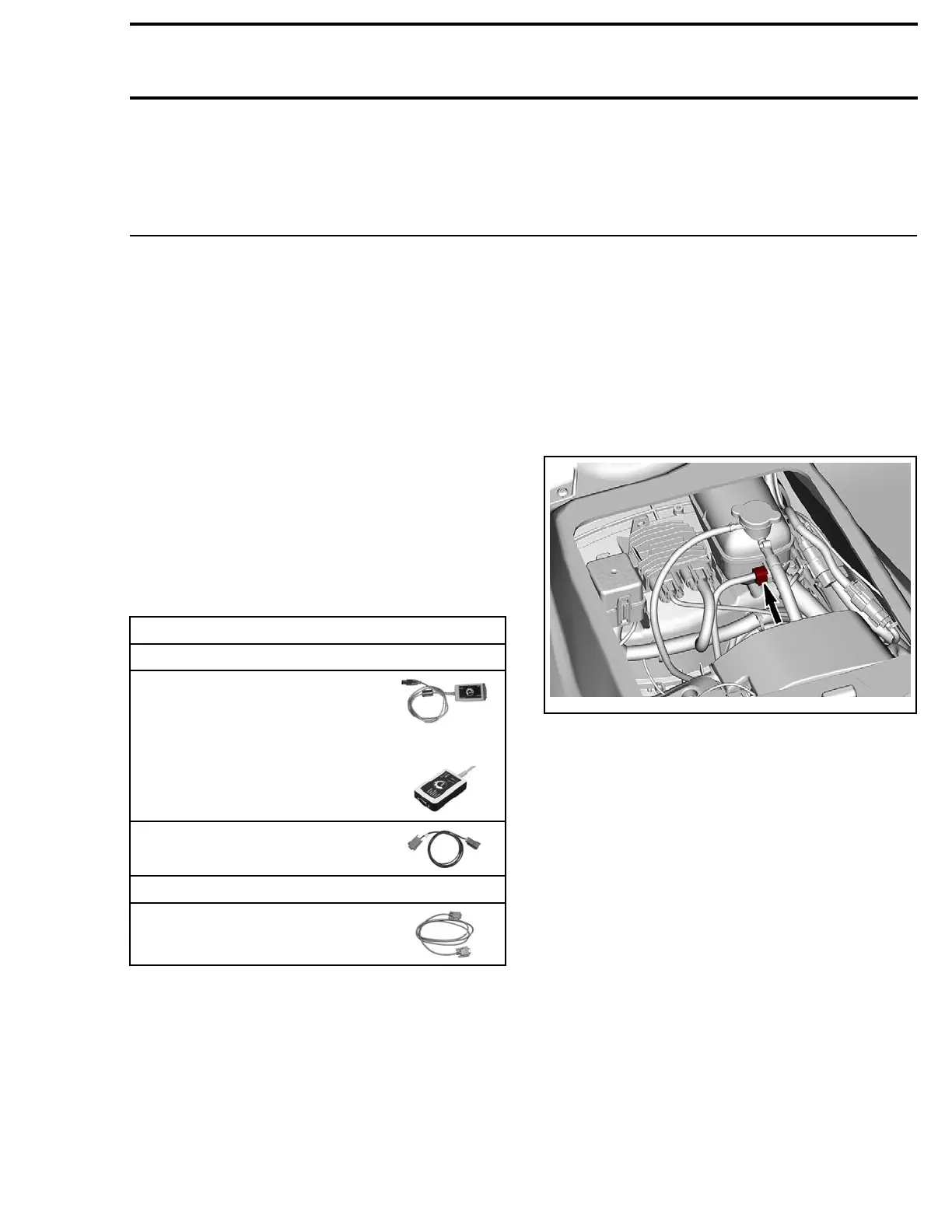
DIAGNOSTIC CONNECTOR
LOCATION
The diagnostic connector is located inside the en-
gine compartment, under the seat, stored in it's
protective cap.
219100963-010-001
TROUBLESHOOTING
Refer to the BRP BUDS chart to ensure you are
using the appropriate hardware and tools.
COMMUNICATION PROBLEMS
MPI Connection Troubleshooting
MPI Status Lights
The MPI includes 2 status lights to show the con-
nection conditions: USB and CAN. Both lights
must be GREEN for the MPI to function properly.
Otherwise, refer to the following charts.
219100963-010 71

 Loading...


