Section 02 ENGINE
Subsection 03 (EXHAUST SYSTEM)
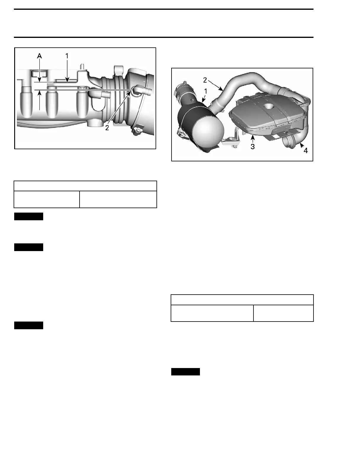
219100893-012-308_a
1. Exhaust manifold rib wall facing the engine
2. Exhaust pipe mark
A. 15 mm (19/32 in)
Tighten exhaust clamp to specification.
TIGHTENING TORQUE
Exhaust c
lamp
11 N•m ± 1 N•m
(97 lbf•in ±9lbf•in)
NOTICE
Do not use pneumatic or electric
tools as seizure may occur.
Install the muffler strap.
NOTICE
Ensure no
t to rotate muffler during
strap ins
tallation. The use of a soapy water so-
lution o
n inner side of muffler strap is recom-
mended.
Install all other removed parts.
After in
stallation, ensure there is no water or ex-
haust ga
s leak when engine is running.
Test run the engine while supplying water to the
exhaust system.
NOTICE
Never ru
n engine without supplying
water to
the exhaust system when watercraft is
out of wa
ter.
EXHAUST HOSES
smr2016-012-002_a
1. Muffler
2. Front exhaust hose
3. Resonator
4. Rear exhaust hose
Replacing the Front Exhaust Hose
Remove seats.
Remove engine service cover.
Cut all locking ties from exhaust hose.
Remove exhaust hose from the muffler outlet a nd
resonator.
Remove front exhaust hose from vehicle.
When reinstalling exhaust hose, make sure to at-
tach elbow fittings at the highest position that you
can on the exhaust hose.
Replace all locking ties previously cut.
Tighten retaining clamps to specification.
TIGHTENING TORQUE
Front exhaust hose clamp
4N•m ± 1N•m
(35 lbf•in ±9lbf•in)
Install all other removed parts.
After installation, ensure there is no water or ex-
haust gas leak when the engine is running. Test
run the engine while supplying water to the ex-
haust system.
NOTICE
Never run engine without supplying
water to the exhaust system when watercraft is
out of water.
Replacing the Rear Exhaust Hose
Remove the resonator. See procedure in this sub-
section.
Loosen clamp securing the rear exhaust hose to
RH fixing plate.
40 219100893-012

 Loading...


