Section 06 STEERING AND PROPULSION
Subsection 04 (DRIVE SHAFT)
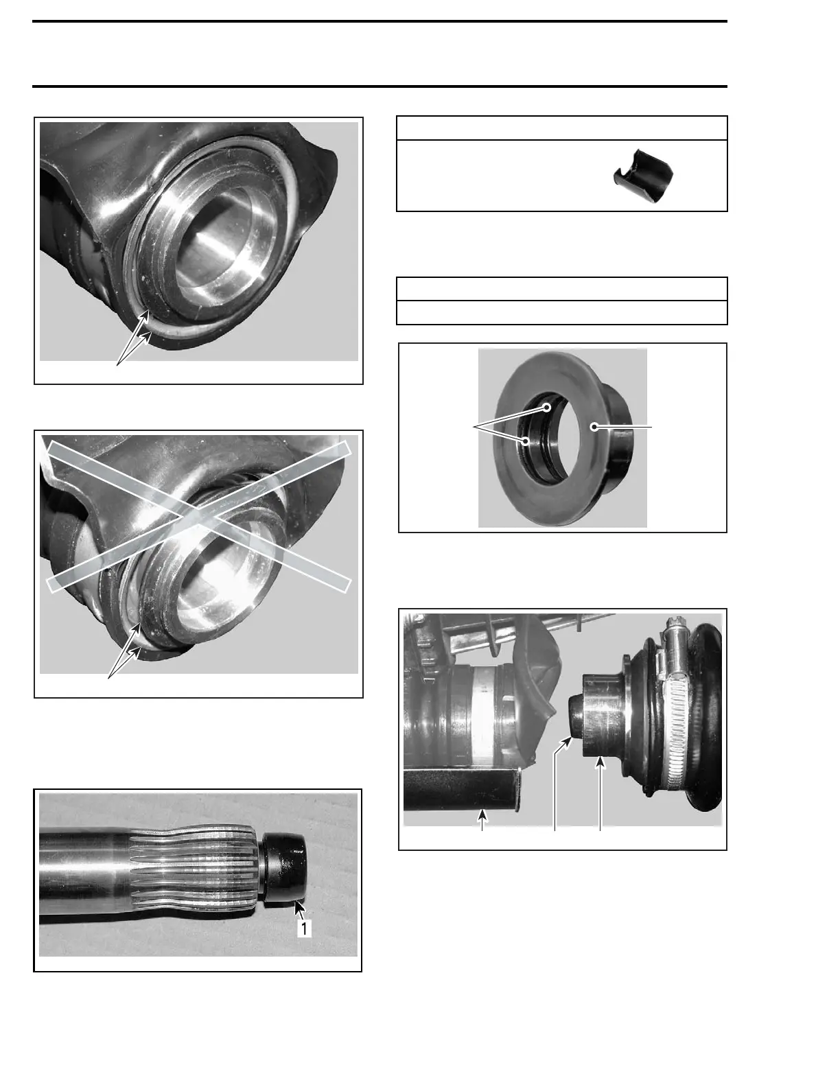
F18I0EA
1
CORRECT POSITION
1. Inner sleeve flush with outer circumferen ce
F18I0FA
1
INCORRECT POSITION
1. Inner sleeve not flush with outer circum ference
Remove the damper at the end of drive shaft and
replaceitwithaNEW one.
smr2006-028-004_a
1. Damper
Ins
tall the PTO support tool on PTO seal assem-
bly
.
REQUIRED TOOL
PTO SUPPORT TOOL
(P/N 529 035 842)
Apply a thin c
oat of lubricant on the floating ring
O-rings. Do n
ot get lubricant on floating ring con-
tact surface
.
SERVICE PRODUCT
P80 GRIP -IT (P/N 296 000 406)
1
F18I0KA
2
1. P80 Grip-it on O-rings
2. No lubrication on contact surface
Slide drive shaft far enough to install floating ring.
F18I0HA
123
1. PTO seal support
2. Driv
e shaft end
3. Insert floating ring on shaft end
Continue pushing drive shaft towards engine care-
fully guiding it in the PTO seal then in crankshaft
splines. It may be necessary to move PTO seal
assembly up and down to position it in the same
axis as the drive shaft.
NOTE: If drive shaft does not enter into the PTO
seal, check engine alignment.
206 219100963-020

 Loading...


