Section 02 ENGINE
Subsection 03 (EXHAUST SYSTEM)
smr2016-012-008_c
Step 1: Install first
Step 2: Insta ll last
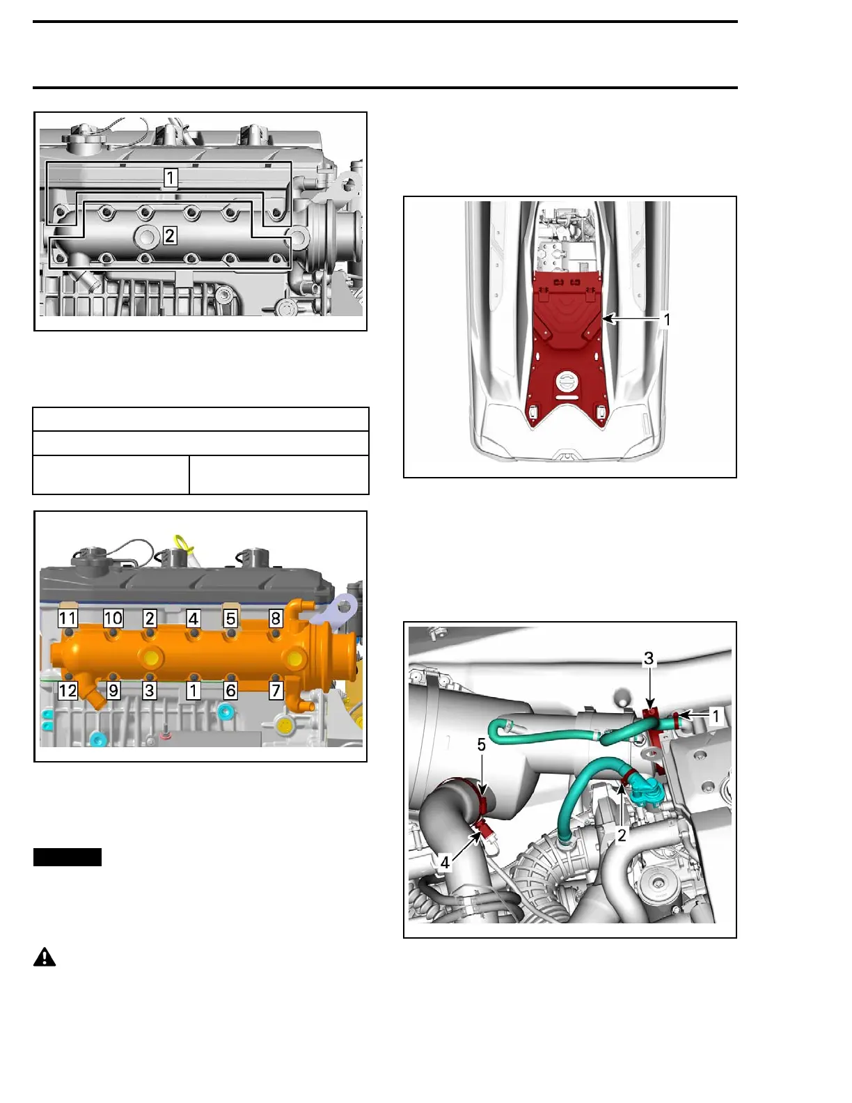
Tighten screws to specification a s per following
illustrated sequence.
TIGHTENIN
G TORQUE
Repeat the procedure twice.
Exhaust manifold
screw
9N•m ± 1N•m
(80 lbf•in ±9lbf•in)
RTX150
3ACEMY18-001-003_a
After installation, ensure t here is no water or ex-
haust gas leak when the engine is running. Test
run the engine while supplying water to the flush-
ing connector.
NOTIC
E
Never run engine without supplying
water to the exhaust system when watercraft is
out of water.
MUFFLER
CAUTION Certain components in the
engine compartment may be very hot. Let
exhaust system cool down prior to removing
parts.
Muffler Access
Remove or open seat.
Remove the engine service cover.
219100893-012-304_a
1. Engine se
rvice cover
Removing the Muffler
1. Remove se
ats.
2. Remove engine service cover.
3. Disconnect the water outlet hose from the ex-
haust manifold.
219100893-012-305_a
1. Water outlet hose (exhaust manifold)
2. Blow-by hose (blow-by valve)
3. Exhaust clamp
4. EGTS sensor
5. Exhaust hose
4. Gently disconnect the hose from blow-by valve.
5. Unscrew exhaust clamp.
38 219100893-012

 Loading...


