Section 09 WIRING DIAGRAM
Subsection 01 (WIRING DIAGRAM INFORMATION)
WIRING DIAGRAM INFORMATION
GENERAL
WIRING DIAGRAM LOCATION
The wiring diagrams are in the back cover pocket.
WIRING DIAGRAM CODES
Wire Color Codes
smr2015-00
9-001_a
1. Wire main color
2. Tracer (thin colored line)
General Wire Color Use
COLOR USE
RED
Battery power (12 Vdc directly
connectedtobattery)
RED + tracer
Fused 12 Vdc power or switched
power from relay
VIOLET or
VIOLET + tracer
Fused 12 Vdc accessory power
from fuse box
YELLOW
Alternating current (AC)
from magneto
BLACK Ground
WHITE/BE IGE
WHITE/BLACK
CAN H I wires,
CAN LO wires
Color Codes
COLOR CODES
CODE COLOR CODE COLOR
BG
BEIGE
(TAN)
OR / OG ORANGE
BK
BLACK
PK PINK
BN
BROWN
RD RED
BU BLUE VT
VIOLET
GN GREEN
WH WHITE
GY GRAY
YE
YELLOW
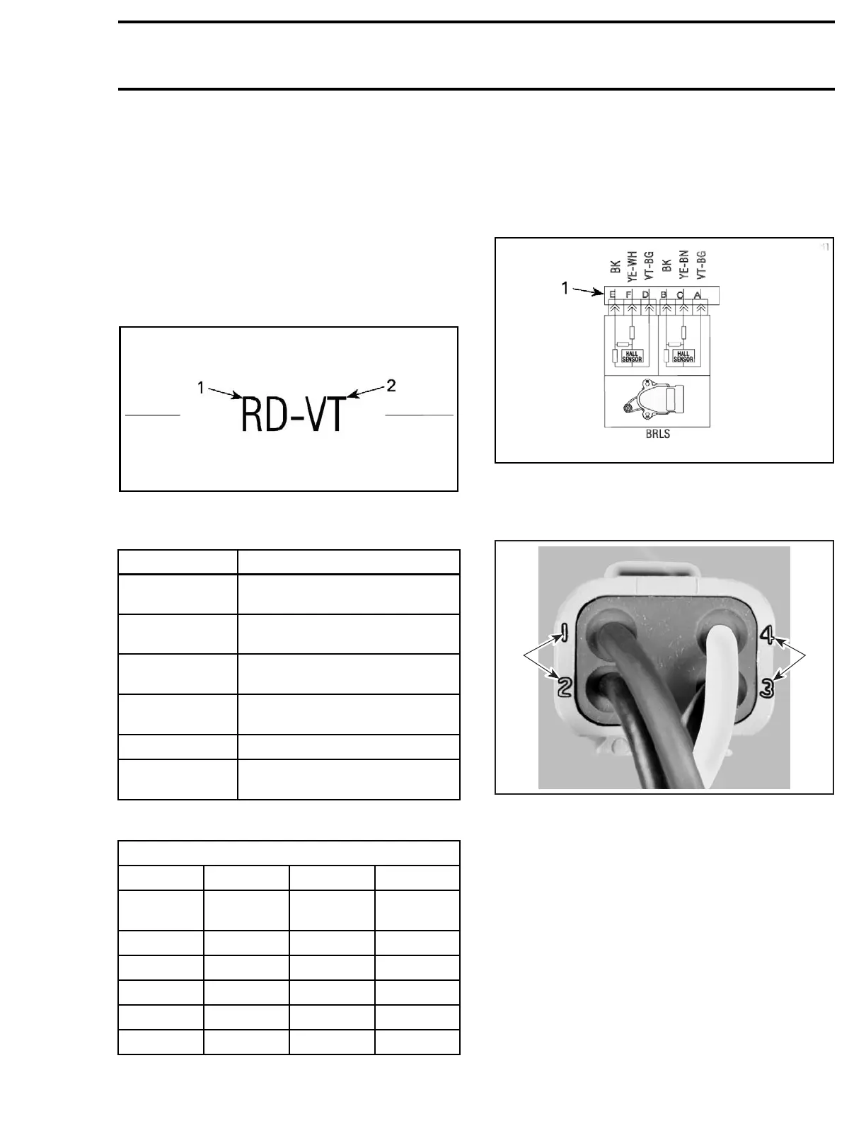
Terminal Identification on Connector
On the wiring diagram, a letter or a digit is used to
identify the terminal position in a connector.
smr2015-0
09-002_a
1. Terminal position
On a connector, a letter or a digit is usually molded
on the connector to identify the terminal position.
F04H6LA
1 1
TYPICAL
1. Wire identification numbers
Terminal Identification on a Wiring
Diagram
In-line connectors of wiring harnesses are identi-
fied on the w iring diagram with their approximate
location and the following information.
smr2016-044 253

 Loading...


