Section 09 WIRING DIAGRAM
Subsection 01 (WIRING DIAGRAM INFORMATION)
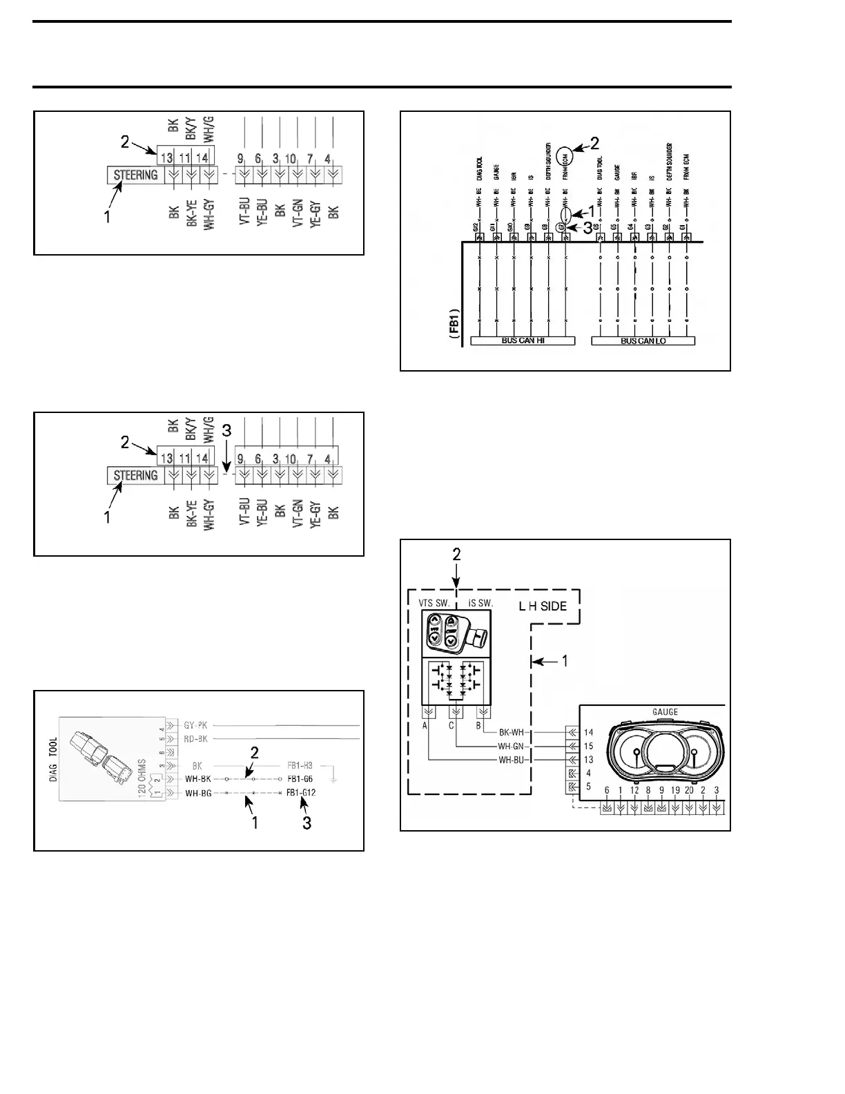
smr2015-009-003_a
TYPICAL
1. Connector location
2. Wire pin location in connector
Connectors Linked by a Dashed Line
Connectors may be divided into segments linked
by dashed lines, however, some segments of the
same connector may be found elsewhere on the
wiring diagram.
smr2015-
009-003_b
TYPICAL
1. Connector identification a nd location
2. Connecto
r pin number
3. Dashed line links connector segm ents as one
CAN Wire Circuit References
On the wiring diagram, CAN linked components
use the following coding.
smr2015-009-004_a
TYPICAL
1. CAN HI wire (x)
2. CAN LOW wire (o)
3. Wire destination
FB1 - G12 = : Terminal G12 in the fuse box no . 1
Corresponding CAN links are identified at fuse box
using the following coding.
smr2012-047-004_a
TYPICAL
1. CAN wire
2. Wire origin
3. Destination terminal (as referenced at ECM)
Component Application
If a component in the wiring diagram is not appli-
cable to every vehicle model, or can be installed
as an option or accessory on certain models, the
component shall be enclosed in a dash line.
smr2011-043-001_a
1. Compo
nent(s) optional or applicable to certain models
2. Indicates each switch i s a s eparate component
254
smr2016-044

 Loading...


