Section 06 ST EE RING AND PROPULSION
Subsection 02 (iBR, REVERSE AND VTS)
SYSTEM DESCRIPTION (VTS)
The VTS system is actually part of the iBR system.
It provides watercraft pitch trim adjustments by
adjusting the vertical position of the jet nozzle.
The VTS can be electrically trimmed to the desired
attitude within the VTS range, or to one of 2 preset
trim positions (on applicable models).
The VTS switch (or Up/Down switch) sends com-
mand signals to the gauge. The gauge converts
them to CAN protocol and sends them through
the CAN bus to the iBR module on the iBR actua-
tor. The actuator then moves the iBR gate which
moves the nozzle to the desired trim position.
NOTE: The nozzle and iBR gate move together
in the VTS trim range up to the maximum noz-
zle down position. If NEUTRAL, BRAKING or RE-
VERSE is engaged, the iBR gate moves past the
VTS full down position. When FORWARD thrust
is reengaged, the nozzle and iBR gate move up to
the last selected VTS trim position.
The nozzle trim position can be seen on the VTS
position indicator in the information center.
NOTE: Changing the VTS trim position only
changes the indication. The nozzle will move
to the selected VTS trim position when forward
thrust is engaged.
iVTS
1
2
219001970-200_b
INFORMATION CENTER — VTS POSITION INDICATOR
1. Bow up
2. Bow down
NOTE: Only the segment indicating the relative
position of the VTS will b e on. The illustration
shows all segments on as can be seen during the
self test function.
The VTS system provides the following features
according to models
– Nozzle trimming
– Selection of 3 preset trim positions
Nozzle Trimming
Watercraft must be operating in forward position.
9 trim positions are available.
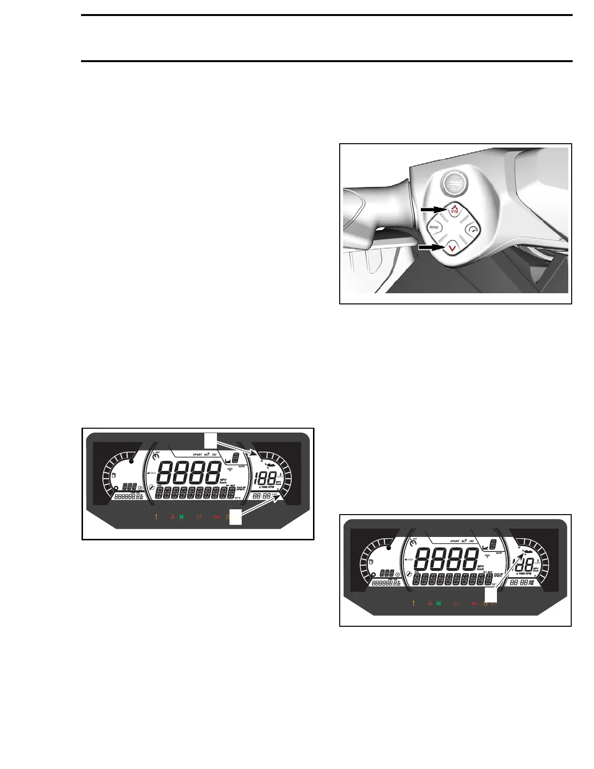
Using the VTS Button
(LH Side of Handlebar)
Press the UP or DOWN arrow button to change
the VTS setting.
219100963-011-002
Using Preset Trim Positions
Three preset trim positions can be selected.
To select the highest trim position, double-click
on the VTS UP arrow button (bow up).
To select the lowest trim position, double-click on
the VTS DOWN arrow button (bow down).
Launch Control (If equipped)
The Launch Control is an automatic adjustment
of the VTS to achieve optimum acceleration.
When the speed is below 20 km/h (12 MPH), the
VTS lowers to it's l owest position and the iVTS
indicator flashes to indicate the system is ready.
When the speed exceed 30 km/h (19 MPH) the
VTS return to the user selected position.
iVTS
1
219001970-200_c
1. Launc
h Control indicator
To activate the Launch Control, press simultane-
ously both the VTS UP and DOWN buttons.
219100963-018 171

 Loading...


