Section 06 STEERING AND PROPULSION
Subsection 02 (iBR, REVERSE AND VTS)
smr2016-036-048_a
5. Reinstall other removed parts. Refer to appro-
priate subsections for procedures.
NOTICE
Allow 24 hours for thread locker on
retaining screws to cure.
Perform
IBR AUTO-CALIBRATION
procedure. Re-
fer to
IBR AUTO-CALIBRATION
in this subsection.
ACTUATOR OUTPUT SHAFT
Removing the Actuator Output Shaft
1. Remove the connecting arm.
2. Unscrew the output shaft (1/4 of a turn) from
the iBR actuator.
Installing the Actuator Output Shaft
The Installation is the reverse of the removal pro-
cedure. However, pay attention to the following.
TIGHTENING TORQUE
Actuator output shaft 4.3 N•m (38 lbf•in)
Make sure the output haft is aligned with the con-
necting arm.
Perform
iBR AUTO-CALIBRATION
procedure. Re-
fer to
IBR AUTO-CALIBRATION
in this subsection.
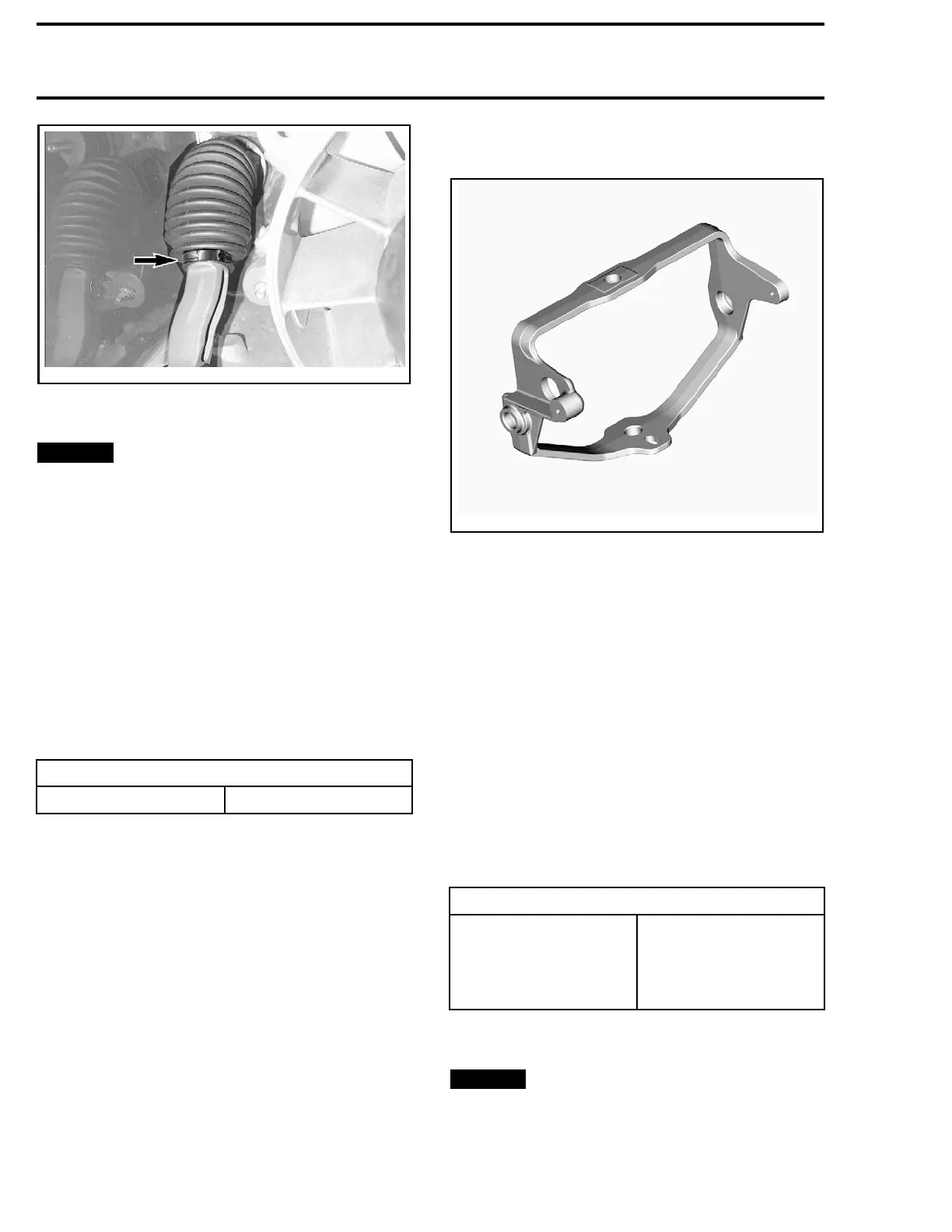
VTS TRIM RING
219100893-029-018_a
Removing the VTS Trim Ring
1. Remove the iBR reverse gate.
2. Disconnect the steering cable from nozzle. Re-
fer to
STEERING
subsection.
3. Remove VTS trim ring screws.
4. Remove nozzle pivot screws (if required).
iDF Models
5. Move the VTS trim ring with nozzle upwards.
6. Using a screwdriver or a ny suitable tool, care-
fully pry out the iDF arm from the VTS trim ring
attachment.
Installing the VTS Trim Ring
The installation is the reverse of the removal pro-
cedure. However, pay attention to the following:
TIGHTENING TORQUE
VTS trim ring screws
27 N•m ± 1 N• m
(20 lbf•ft ± 1 lbf•ft)
+
LOCTITE 271 (RED)
(P/N 293 800 005)
Reinstall other removed parts. Refer to appropri-
ate subsections for procedures.
NOTICE
Allow 24 hours for thread locker on
screws to cure.
Perform
IBR AUTO-CALIBRATION
procedure. re-
fer to
IBR AUTO-CALIBRATION
in this subsection.
180 219100963-018

 Loading...


