Section 06 ST EE RING AND PROPULSION
Subsection 02 (iBR, REVERSE AND VTS)
219100893-029-012_a
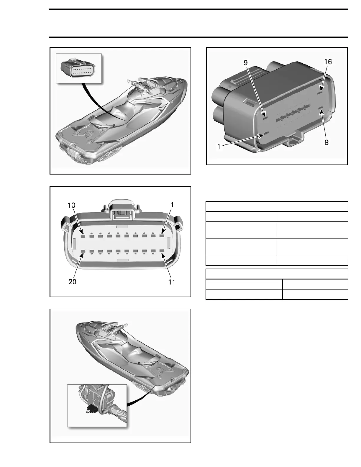
STEERING CONNECTOR LOCATION
smr2014-030-012_a
STEERING CONNECTOR
219100893-029-013_a
IBR ACTUATOR CONNECTOR LOCATION
219100893-029-014_a
IBR ACTUATOR CONNECTOR
iBR ACTUATOR
Specifications
IBR ACTUATOR CONNECTOR
PIN SIGNAL
iBR-1
Battery voltage
(Hot at all t imes )
iBR-2
Battery voltage
(Hot with main relay on)
iBR-8
Ground
iBR ACTUATOR CURRENT DRAW
DOWN SELECTION
-5 to -15 A
UP SELEC
TION
+10to+20A
Testing iBR Actuator Operation
1. Connect the vehicle to the BRP diagnostic soft-
ware (BUDS2).
2. In BUDS
2, go to:
– Functions page
– iBR button
– Funct
ions tab
– Move iBR Up/Down
3. Click
iBR UP and iBR DOWN buttons alter-
natel
y and look for a change in iBR Position
(Deg
).
If the iBR moves using these buttons but does not
move using the iBR lever, test
BRLS VOLTAGE
in
this subsection.
If the iBR does not move, check the iBR fuse(s)
in fuse box. If fuse(s) are good, check power and
ground circuits.
219100963-018 175

 Loading...


