Section 02 ENGINE
Subsection 03 (EXHAUST SYSTEM)
NOTICE
Do not use pneumatic or electrical
tools as seizure may occur.
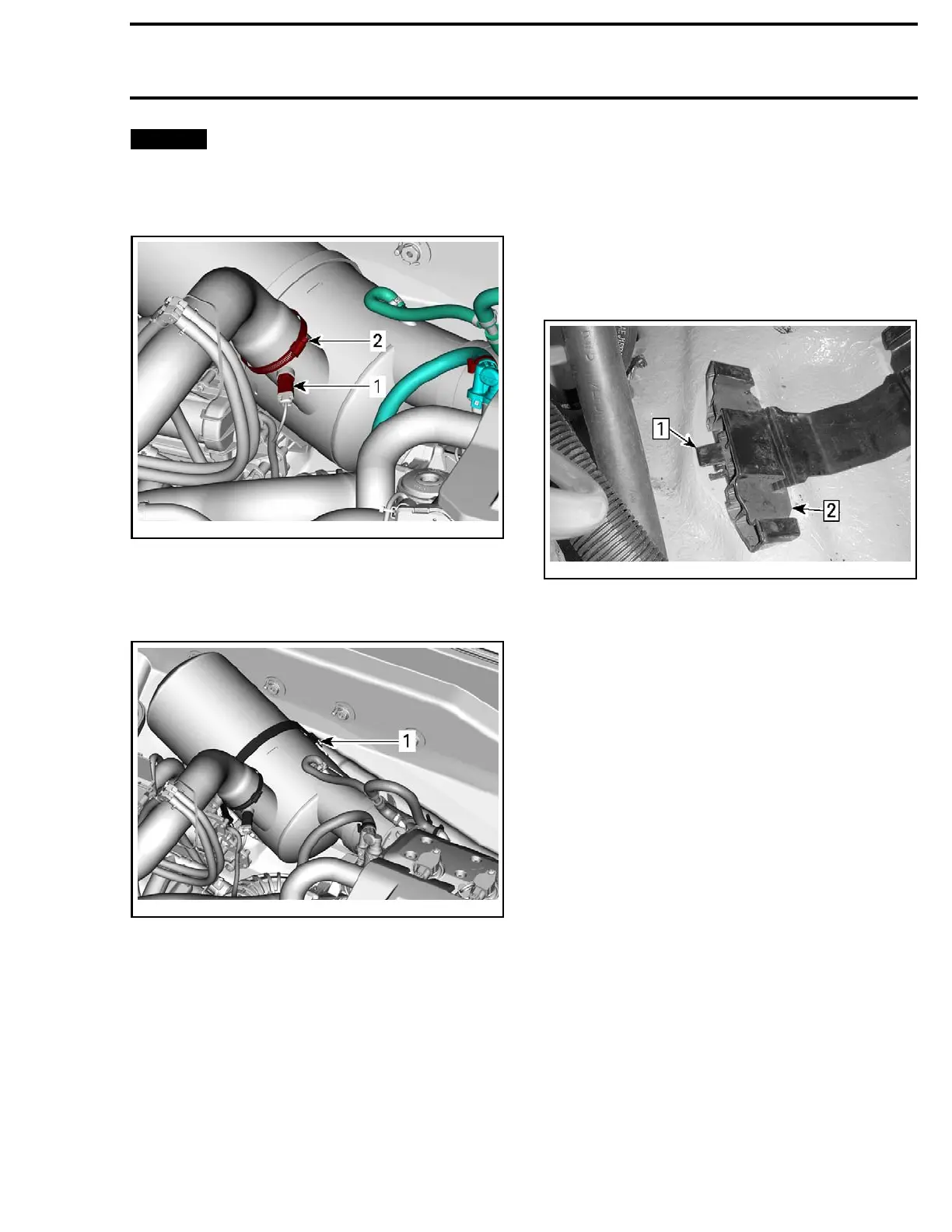
6. Unplug the exhaust gas temperature sensor
(EGTS).
219100893-012-306_a
1. EGTS sensor
2. Exhaust hose clamp
7. Disconnect the exhaust hose from muffler.
8. Detach retaining strap.
219100893-012-307_a
1. Muffler retaining strap
9. Move
the muffler back then slide it forward
thr
ough the deck opening.
Inspecting the Muffler
Chec
k muffler for:
– Cracks
– Corrosion
–Oth
er damages.
Check if exhaust hose i s:
–Bri
ttle
–Hard
–Cracked
– Otherwise damaged.
Replace any defective part.
Installing the Muffler
With a new muffler, install the EGTS sensor. Re-
fer to this subsection.
Open muffler adjusters by sliding adjuster blocks.
smr2008-0
13-026_a
TYPICAL – RUBBER PAD REMOVED FOR CLARITY PURPOSE
Step 1: Lift adjuster tab
Step 2: Mov
e adjuster outward
Insert the muffler in hull.
Align the e
xhaust pipe flange with the exhaust
manifold.
Rotate and move muffler so that the
exhaust pi
pe flange makes perfect contact with
exhaust m
anifold.
Slide both adjuster blocks against muffler to sup-
port it in position.
NOTE: Ensure muffler is in contact with both ad-
juster blocks. Readjust as required.
Install e
xhaust clamp with the nut upward.
Tighten clamp loosely.
Align the exhaust pipe mark with the mark on the
exhaust manifold.
219100893-012 39

 Loading...


