Section 06 ST EE RING AND PROPULSION
Subsection 04 (DRIVE SHAFT)
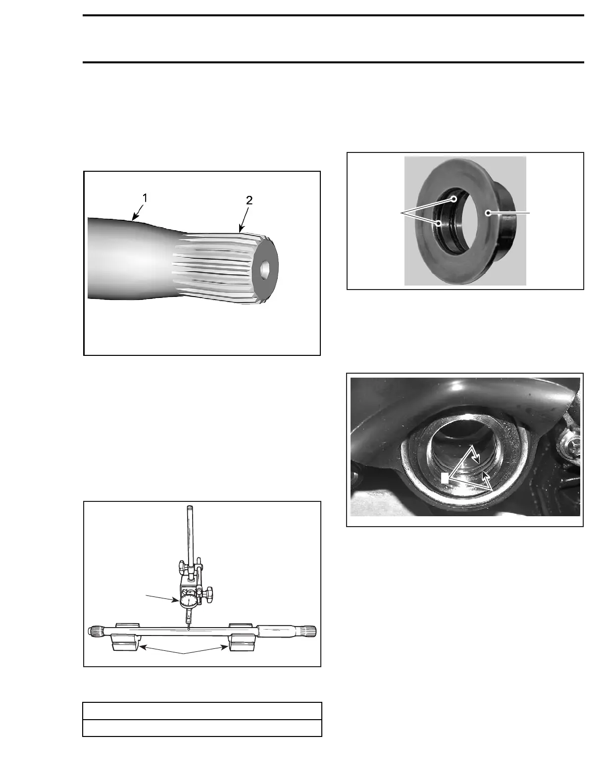
Inspect condition of drive shaft splines. If splines
are damaged, replace drive shaft and check
splines of impeller and PTO housing.
With your finger nail, feel machined surface of
drive shaft. If any irregular surface is found, re-
place drive shaft.
smr2017-339-001_a
TYPICAL
1. Surface c
ondition
2. Splines condition
Place drive shaft on V-blocks and set-up a dial
gauge in center of shaft. Slowly rotate shaft; dif-
ference between highest and lowest dial gauge
reading is deflection. Refer to the following illus-
tration.
NOTE: Excessive deflection could cause vibra-
tion and damage to drive shaft splines, impeller
or floating ring.
1
2
F01J15A
MEASURING DRIVE SHAFT DEFLECTION
1. Dial gauge
2. V-blocks
MAXI
MUM DEFLECTION
0.5mm (.02in)
Floating Ring
Inspect condition of O-rings and contact surface
of floating ring.
Replace as required.
1
F18I0KA
2
1. O-rings
2. Contact surface
Installin
g the Drive Shaft
Before installing drive shaft, discard both O-rings
inside PTO seal and install NEW ones.
F18C01A
1
1. O-rings
Inspect PTO seal assembly. The inner sleeve
must be flush with outer circumference of the
assembly. Otherwise, gently push or tap on inner
sleeve until flush.
219100963-020 205

 Loading...


