Section 05 ELECTRICAL SYSTEM
Subsection 02 (WIRING HARNESS AND CONNECTORS)
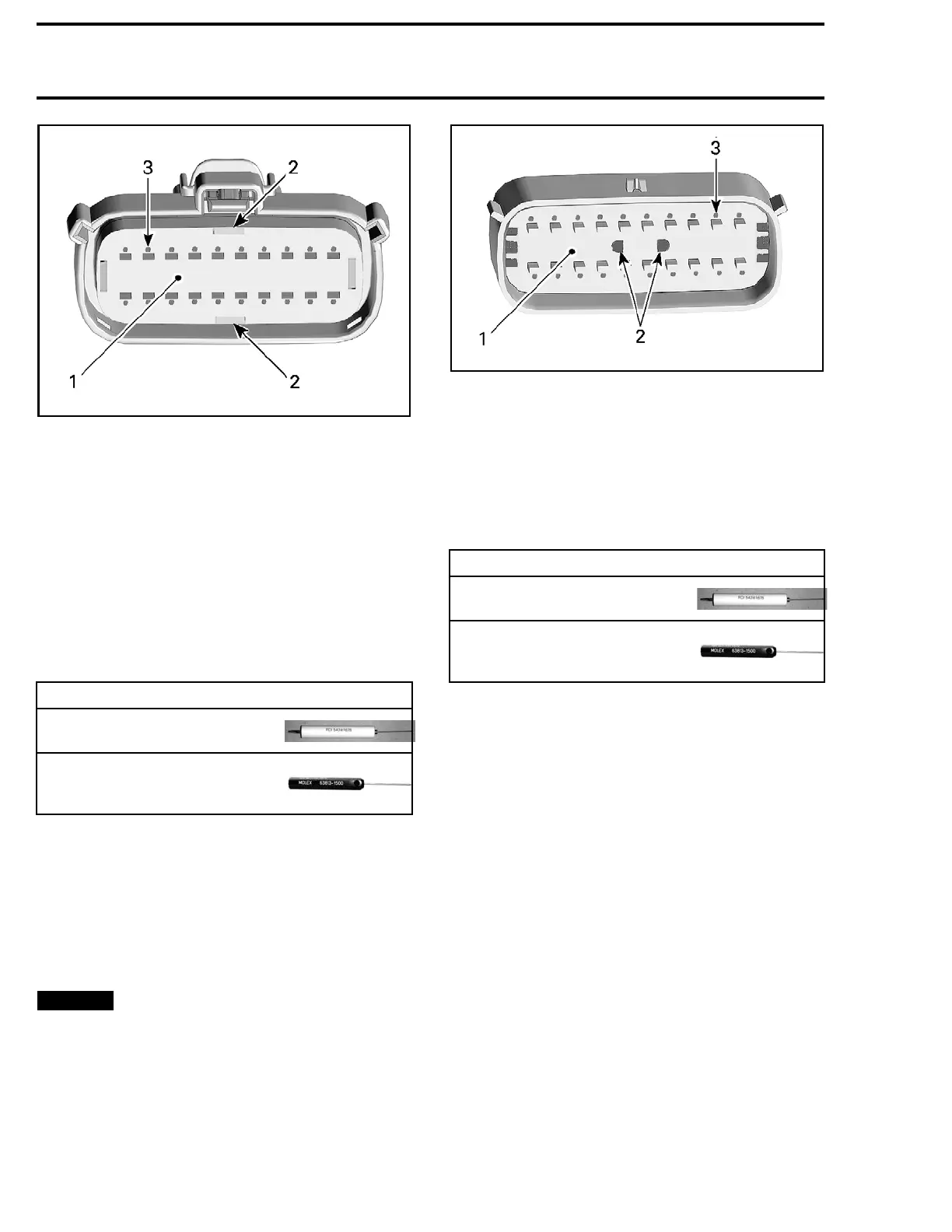
smr2014-030-012_b
1. Socket locator
2. Pry holes
3. Holes for inserting terminal extractor tool
2. Carefully pull out the socket locator out to the
detent position (approximately 5 mm).
NOTE: Do not remove the socket locator from the
connector housing.
3. Insert the extractor tool in the small hole adja-
cent to the socket.
NOTE: Push the extractor tool in only as far as re-
quired to release the lock from the socket. The
tool should s lide along the socket and be inserted
between the socket and the lock.
REQUIRED TOOL
FCI TERM
INAL EXTRACTOR
TOOL (P/N 54241678) or,
MOLEX 15
0TERMINAL
EXTRACTOR TOOL (P/N 63813
- 1500)
4. Gently
pull on the wire to extract the socket out
the bac
k of the connector.
Extracting the Pin (Male Connector)
1. Using
a pair of thin long nose pliers, pull the
pin lo
cator out to the detent position (approxi-
matel
y 5 mm). This will allow unlocking of the
pins.
NOTICE
Do not attempt to remove the pin lo-
cator or damage will occur. Be careful not to
bend the pins when using the pliers.
smr2014-045-002_a
1. Pin locator
2. Insert long nose pliers here
3. Holes for inserting terminal extractor tool
2. Insert the extractor tool in the small hole adja-
cent to the pin.
NOTE: Push the extractor tool in only as far as
required to release the lock from the pin. The
tool should slide along the pin and b e inserted
between the pin and the lock.
REQUIRED TOOL
FCI T E RM I NAL EXTRACTOR
TOOL (P/N 54241678) or,
MOLEX 150 TERMINAL
EXTRACTOR TO OL (P/N 63813
- 1500)
3. Gently pull on the wire to extract the pin out the
back of the connector.
Inserting the Pin
1. Ensure the terminal (pin) is properly crimped
onto the wire.
2. Ensure
the pin locator (the white plastic insert
in the c
onnector) is out in the detent position.
3. Insert the pin in through the back of the connec-
tor.
NOTE: When inserting the pin, insert the
stepped portion facing the notch in the con-
nector pin hole.
118 219100963-012

 Loading...


