Section 05 ELECTRICA L SYSTEM
Subsection 04 (STARTING SYSTEM)
SOLENOID DYNAM
IC TEST (ENGINE CRANKING)
TEST PROBES VOLTAGE (DC)
Solenoid
starter post
Battery groun
d
Battery volta
ge
M
1
2
smr2009-034-010_b
1. Starter motor
2. Starter solenoid
9. If test failed, carry out a
TESTING SOLENOID
INPUT VOLTAGE
.
10. If test succeeded, continue with next step.
SOLENOID D
YNAMIC TEST (ENGINE CRANKING)
TEST PROBES VOLTAGE (DC)
Solenoid
battery post
Solenoid
starter post
0.2 Vdc ma
x.
M
1
2
smr2009-034-010_c
1. Starter motor
2. Starter solenoid
If test failed, replace solenoid.
If all solenoid dynamic tests are as specified, re-
place starter.
11. Remove rubber band from throttle lever.
12. Attach the electrical component support to the
battery holder. Refer to
ELECTRICAL COM-
PONENT SUPPORT
in
CHARGING SYSTEM
subsection.
13. Reinstall removed parts.
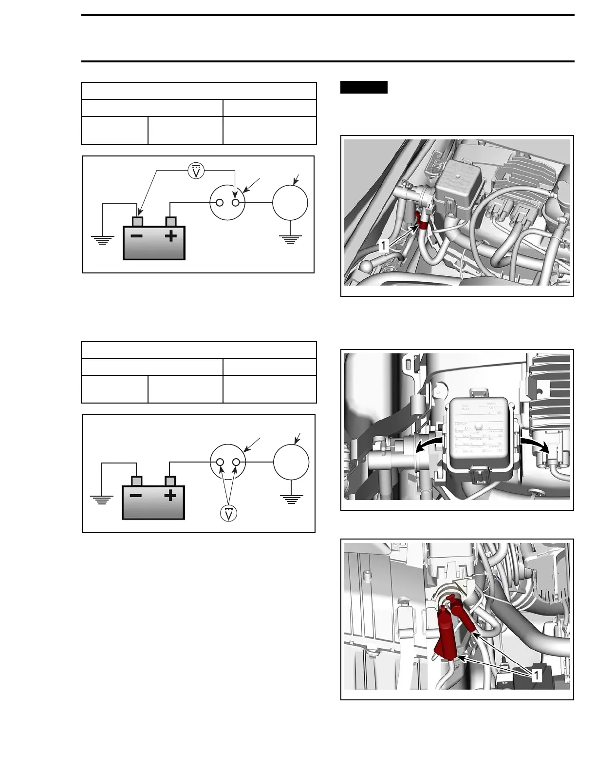
Removing the Solenoid
1. Disconnect battery. Refer to
CHARGING SYS-
TEM
subsection.
NOTICE
Always disconnect the BLACK (-)
battery cable first and reconnect last.
Disconnect solenoid connector.
219100893-
025-003_a
1. Starter solenoid connector
2. Set aside fuse box by opening the tabs and lift-
ing it.
219100893-025-004_a
3. Disconnect solenoid cables.
219100893-025-006_a
1. Cab
les
Lift starter solenoid.
219100963-014 133

 Loading...


