Section 02 ENGINE
Subsection 03 (EXHAUST SYSTEM)
Testing the EGTS Resistance
1. Remove the parts required to access the EGTS.
2. Disconnect the connector from the EGTS.
3. Measure the resistance of the sensor.
EGTS RESISTANCE TEST
EGTS PIN MEASUREMENT
1
2
Refer to
EGTS
RESISTANCE
CHART
smr2008-023-018_a
The resistance should be as per the
EGTS RESIS-
TANCE CHART
that follows. Otherwise, replace
the EGTS.
If the EGTS resistance is within specifications,
proceed with the following steps.
4. Reconnect the EGTS.
5. Disconnect ECM-B connector from the ECM
and install it on the ECM adapter tool.
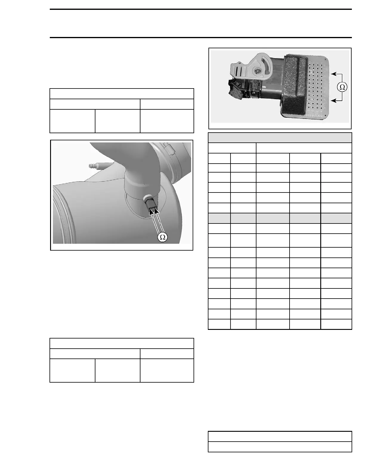
6. Check the circuit resistance as per following ta-
ble.
EGTS RESISTANCE TEST AT ECM
ECM ADAPTOR PIN MEASUREMENT
B-F3
B-G4
Refer to
EGTS
RESISTANCE
CHART
vmr2008-022-005_a
EGTS RESISTANCE CHART
TEMPERATURE RESISTANCE (OHMS)
°C °F NOMINAL LOW HIGH
- 30 - 22 12600 11800 13400
-20
-4
11400 11000 11800
-10
14
9500 8000 11,000
0 32 5900 4900 6900
10 50 3800 3100 4500
20 68 2500 2200 2800
30 86 1700 1500 1900
40 104 1200 1080 1320
50 122 840 750 930
60 140 630 510 750
70 158 440 370 510
80 176 325 280 370
90 194 245 210 280
100 212 195 160 210
110 230
145
125 160
120 248
115
100 125
If resistance value is as specified, check ECM. Re-
fer to
ENGINE CONTROL MODULE (ECM)
sub-
section.
If resistance value is not within specifications, re-
pair or replace wiring and connectors between the
ECM and the EGTS.
Replacing the EGTS
1. Disconnect the EGTS connector.
2. Un
screw EGTS from muffler.
3. Apply Loctite 518 on the middle threads of the
new EGTS.
SERVICE PRODUCT
LOCTITE 518 (P/N 293 800 038)
219100893-012 35

 Loading...


