VISOR
®
Communications manual
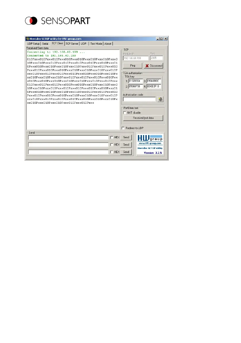
Fig. 12: Data output, Ethernet, Tool / 3
The data visible here are set under "Data output":
l Trailer "010"
l Overall result of Detector 1 (here, a "P" for positive, since test condition: brightness fulfilled)
l Trailer "xxx"
4.2 Example: Commands (requests) from PC / PLC to VISOR
®
With acknowledge / data output from VISOR
®
Step 1
For better clarity, the triggered operation is switched to here for Example 2. This can be done as
follows: Under Job/Image acquisition/Trigger mode = Set Trigger. Otherwise, the settings from
Ethernet example 1 will remain the same in the VISOR
®
.
Page 24 EN 06814859 - 1/24/2019-00