Maintenance and Troubleshooting
Troubleshooting
120 SSU-2000 User’s Guide 12713020-002-2 Revision D – April 2004
Troubleshooting the SDU-2000
The buffer module in the SDU-2000e collects status information from the Output
modules and relays status messages to the SSU-2000. The status messages alert
the SSU-2000 when a possible problem exists; they can be accessed through the
SSU-2000 using a terminal or PC using a terminal emulation software. Refer to
Establishing a Connection With the SSU-2000, on page 88, for more information on
connecting to an SSU-2000 for troubleshooting. Table 5-4 outlines troubleshooting
procedures for the SDU-2000.
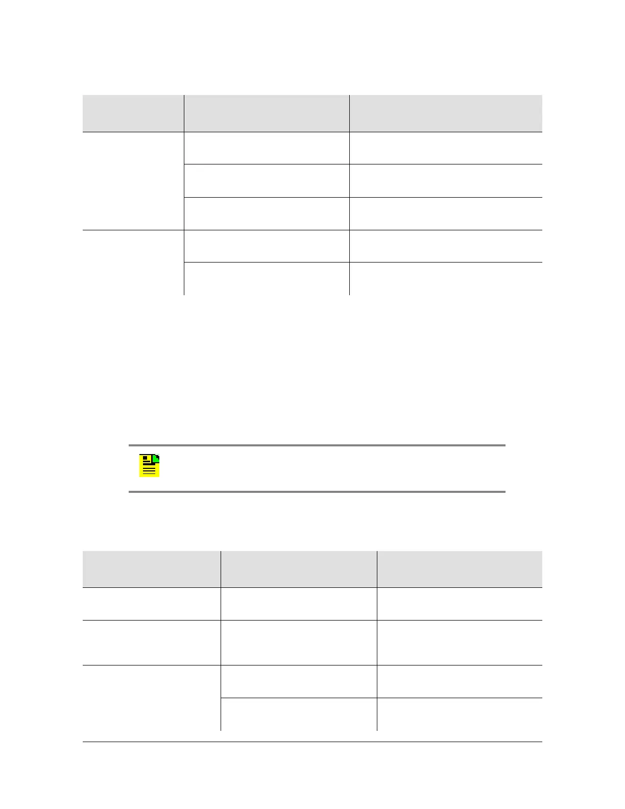
Any amber LED on
Input module
No signal to the input panel Ensure signals are properly routed to
the input panel.
No input signal on cable
connected to I/O adapter panel.
Replace no-signal cable with signaled
cable.
I/O adapter panel is not
connected to the Input module.
Connect the I/O adapter panel to the
Input module.
No output signal on
the output panel
Port is not turned on. Use the appropriate command to turn
the port on.
The I/O adapter panel is not
connected to the Output module.
Connect the I/O adapter panel to the
Output module.
Note: If fault isolation and corrective action have been performed and
the problem persists, contact Symmetricom Global Services.
Table 5-4. SDU-2000e Troubleshooting Procedures
Symptom Probable Cause
Troubleshooting
Procedure/Corrective Action
Output module Fault
indicator is on
Loose module Re-seat module.
Output module Fault
indicator is flashing Amber
Fault on distribution cabling Verify that cabling is connected
properly. Replace cabling as
needed.
Output module Source
indicator is amber
Loss of clock signal Ensure cabling to main chassis is
secure and correctly installed.
Clock modules in main chassis
are in Warm-up mode
No action necessary.
Table 5-3. SSU-2000 Troubleshooting Procedures (Continued)
Symptom Probable Cause
Troubleshooting
Procedure/Corrective Action

 Loading...