Installing the SSU-2000
Making Connections
66 SSU-2000 User’s Guide 12713020-002-2 Revision D – April 2004
Power Input
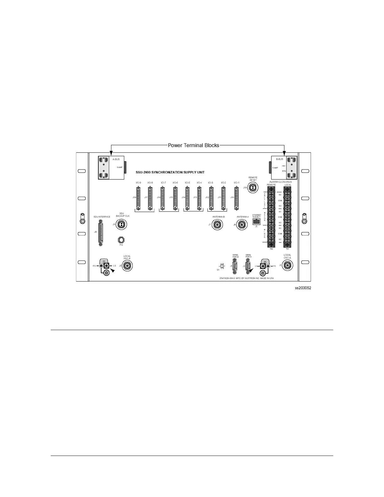
1. Locate the power terminal blocks on the rear panel, as shown in Figure 2-3.
2. Remove both 5 A fuses. You will replace them at the end of the installation
procedure.
3. Using 16 AWG (minimum) stranded wire, connect primary power to the A-BUS
screws and the secondary power to the B-BUS screws. Symmetricom
recommends that you use a #6 spade lug termination for each power lead.
Figure 2-3. Power Terminal Blocks
Making Connections
Making I/O Connections
The SSU-2000 shelf has I/O interface connections for connecting the SSU-2000 to
the corresponding I/O adapter panels. Refer to Chapter 7, Input Module Reference
Data, and Chapter 8, Output Module Reference Data, for information regarding the
different type I/O adapter panels available and the associated cables used to
connect the SSU-2000 to the I/O adapter panels. Figure 2-4 shows the rear panel of
the SSU-2000.

 Loading...