12713020-002-2 Revision D – April 2004 SSU-2000 User’s Guide 205
Output Module Reference Data
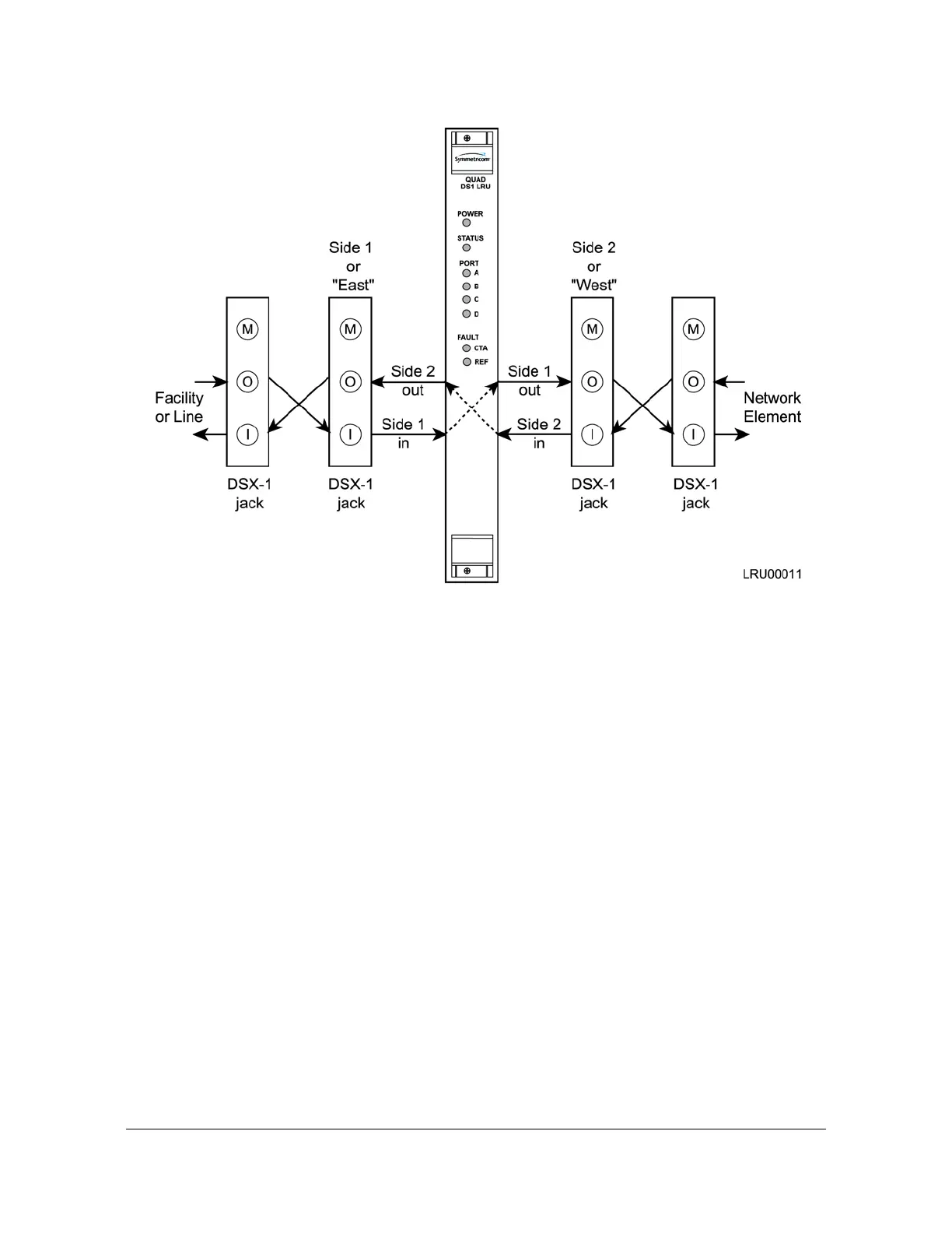
Line Retiming Unit (LRU)
Figure 8-16. Recommended Installation Schematic for the LRU
Functional Overview
The Line Re-timing Module (LRM) consists of the following functional blocks:
Power input regulation
Microcontroller unit
Memory (FLASH and RAM)
LED indicators (module and port status)
Figure 8-17 is a block diagram of the DS1 LRU module.

 Loading...