12713020-002-2 Revision D – April 2004 SSU-2000 User’s Guide 415
Signal Names and Definitions
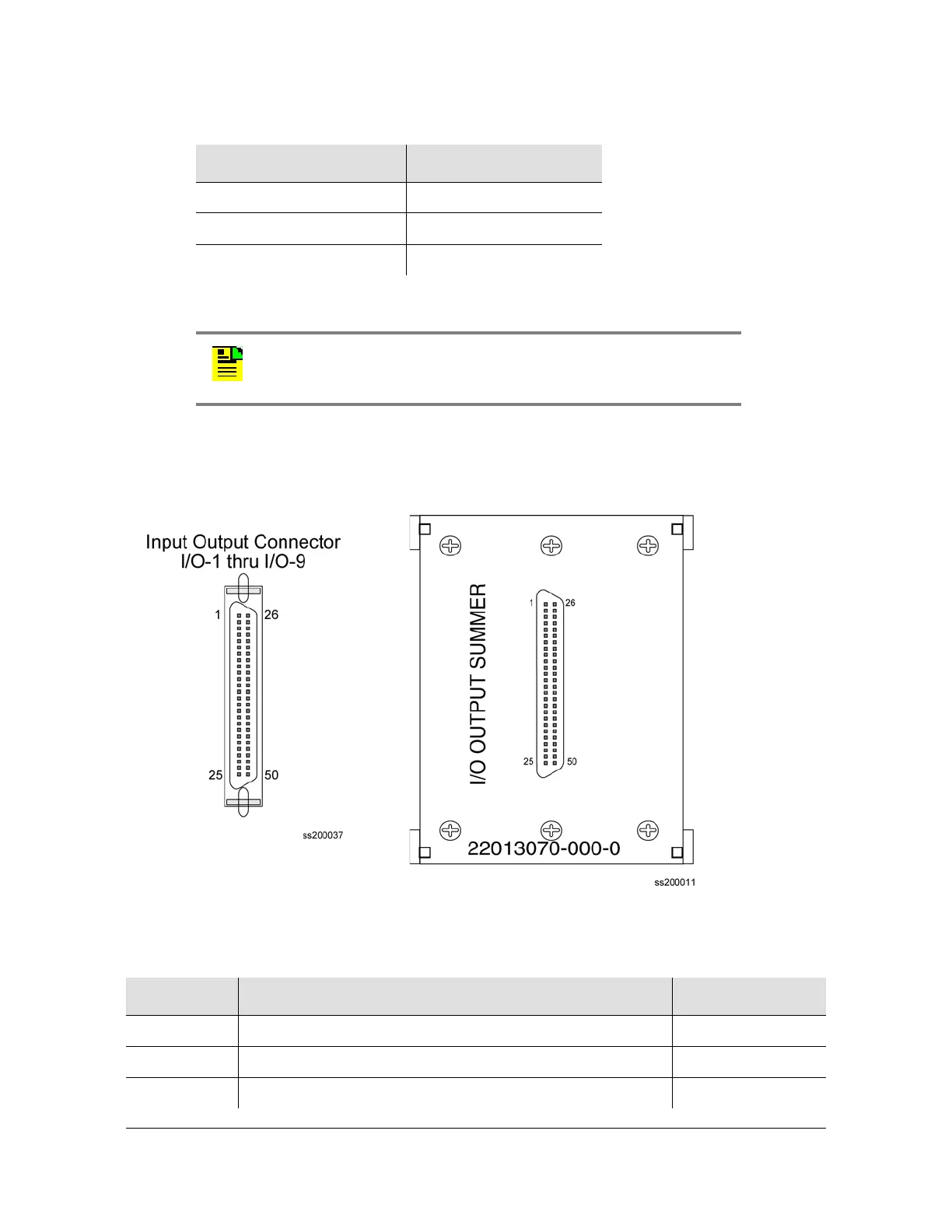
Table D-7 outlines input and output signal definitions on connectors J10 through
J18, which are the nine 50-pin connectors located on the rear panel of the
SSU-2000 Main shelf.
Figure D-7. I/O Connector and Summer Adapter Pinouts
J16 A9
J17 A10
J18 A11
Note: The pin assignments for J10 through J18 are identical. The
pin assignments outlined in Table D-7 refer to all nine of these
connectors.
Table D-7. 50 Pin Connector Input/Output Signal Names and Location
Name Description Connector Pin #
Cs Fault Logic Level Input Indicating Problem with Cs Reference 1
Cs Fault RTN Return Line for Cs Fault Signal 26
ITIP 01 Tip Connection of Input Signal # 1 3
Table D-6. I/O Slot Locations (Continued)
Rear Panel Connector I/O Slot Location

 Loading...